ELECDURA NETWORK

Your Whole New Supply Chain For Heavy-Duty Parts
Whatsapp:
+86 18915027366
Phone:
+86 18915027366
Views: 0 Author: Site Editor Publish Time: 2026-07-23 Origin: Site
“24 volt alternator” is a starting description, not a complete replacement specification. Heavy-duty buyers must also verify output requirement, mounting and pulley geometry, rotation and cooling, regulator behavior, terminals, remote-sense or communication features, operating environment, and the evidence attached to the exact part number. A wrong unit can fit the bracket yet undercharge, overcharge, misalign the belt, damage cables, or create control-system faults.
This revised guide organizes selection into a documented application packet, sample review and release process for trucks, buses, construction machines, agricultural equipment and industrial engines.
Record the battery arrangement, nominal system voltage, installed alternator label and equipment documentation. Two 12-volt batteries may be wired in series for a 24-volt system, in parallel for a 12-volt system, or used in a more complex starting and accessory arrangement. Do not infer system voltage from battery count alone.
Confirm the regulator set-point basis and any temperature compensation, remote sense, battery isolator, equalizer, master disconnect or conversion equipment. If the machine has been modified, document the current wiring rather than assuming the factory configuration remains intact.
Selection field | Record from the application | Supplier evidence |
|---|---|---|
Identity | Installed part, brand, suffix, equipment, engine and serial range. | Quoted manufacturer reference and traceable cross source. |
Electrical | Nominal voltage, required output, loads, duty and regulator/control features. | Rated data, applicable output evidence, terminal map and regulator description. |
Mechanical | Mounting ears, pilot, clocking, pulley, grooves, shaft and belt line. | Controlled drawing and sample measurements from defined datums. |
Environment | Temperature, dust, water, vibration, speed range and service access. | Application statement and protection or cooling details. |
Commercial | Quantity, destination, schedule and packaging needs. | MOQ, lead time, Incoterm, warranty, traceability and change control. |
List continuous and intermittent loads: engine and vehicle controllers, lighting, HVAC blowers, cab accessories, pumps, fans, heaters, telematics, body equipment and battery recovery after starting. Consider duty at idle as well as rated engine speed. A high nameplate amp rating does not guarantee adequate output at the alternator speed and temperature where the equipment spends most of its time.
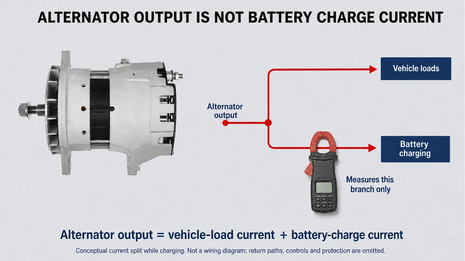
Use the equipment maker’s requirement and an applicable alternator output curve when available. Keep reserve for battery recharge and transient loads without assuming the largest alternator will automatically work. Higher output can change belt demand, heat, cable and protection requirements.
Charging voltage and output must be interpreted with battery state, load, speed, temperature and circuit losses. This illustration provides no universal pass limit.
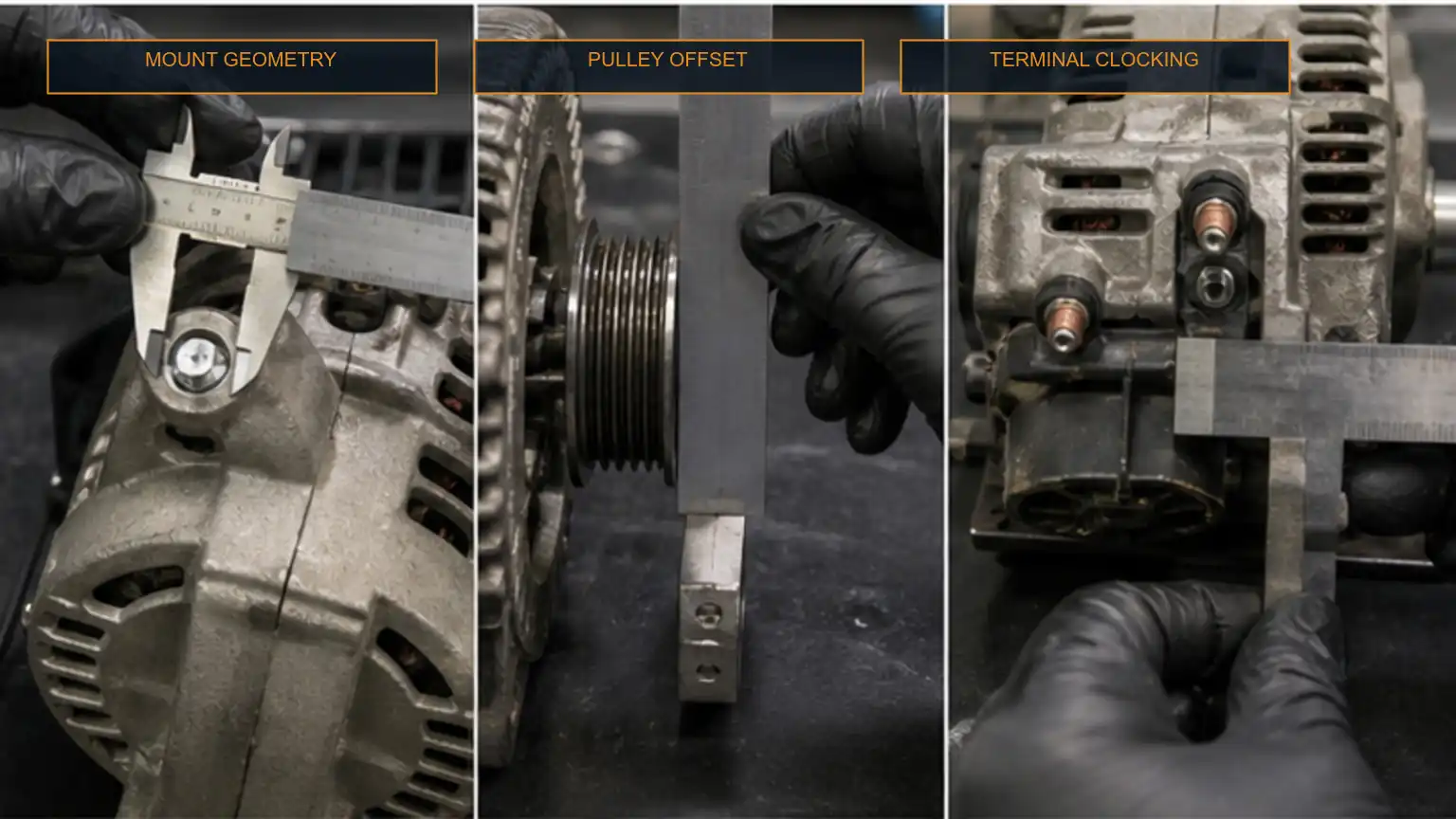
Compare the mounting style, ear width, hole diameters, spacing, pivot and adjuster arrangement, pilot features, housing clocking and rear clearance. Record pulley diameter, grooves, belt type, shaft and retaining method. Verify rotation and any fan or cooling orientation required by the design.
Pulley ratio determines alternator speed. A pulley change can affect low-speed output, maximum alternator speed, belt wrap and bearing load. Do not move a pulley from the old unit until the manufacturer confirms compatibility and the retention procedure. Misalignment that seems small during installation can accelerate belt, pulley and bearing failure.
Measure from documented datums and compare with the approved drawing. The staged image is not an interchange authorization.
Map the main output terminal, ground path, ignition or excite circuit, warning-lamp circuit, sense terminal, phase or tachometer signal and any network or smart-regulator connection. Terminal appearance and connector shape are not enough; pin function and control strategy must match.
Remote sense can compensate for voltage drop at a defined point, but an incorrect or open sense circuit can alter charging behavior. Delco Remy’s literature library separates alternator selection, remote-sense and heavy-duty diagnostic materials, illustrating why one family photo cannot answer every electrical question. Use the applicable manufacturer document for the quoted unit.
Inspect battery condition, cable size, terminals, grounds, disconnects, fuses or protection devices and harness routing. Heat, corrosion, loose connections and undersized conductors can create voltage loss and misleading charge complaints. Test voltage drop under a relevant load using the equipment procedure; resistance checks on an idle circuit may miss the fault.
A replacement alternator should not be used to mask a battery, cable or load-management problem. The alternator output and amp testing guide explains the system boundary and recording needs.
Ask the supplier to identify the offered manufacturer, condition, country or plant statement, part number, revision and the source of any cross-reference. Require a drawing, terminal map, electrical data, sample label and packaging plan. If the unit is remanufactured, define core acceptance, replaced components, wear limits, testing, marking and warranty separately from a new-unit program.
Evidence gate | Pass condition | Hold condition |
|---|---|---|
Cross-reference | Source and supersession reconcile with the application. | Only an undated seller list or visual match. |
Interfaces | Drawing and measured sample match mounting, pulley and terminals. | An important datum or pin function is unresolved. |
Performance | Applicable output and regulator evidence states test conditions. | Only voltage and maximum amps appear on a label. |
Lot control | Label, lot traceability, final test and change notice are defined. | Supplier may silently change critical components. |
Commercial release | Terms, packaging, warranty and discrepancy route are written. | Low price is the only controlled field. |
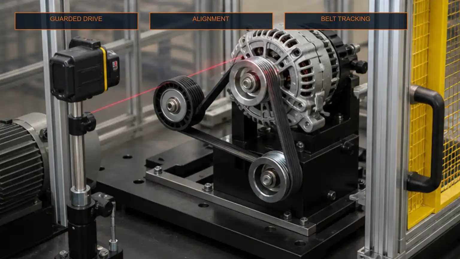
Assign a sample ID and document the carton, label, lot code, casting, terminals, pulley and mounting points. Compare controlled dimensions before installation. If bench testing is justified, use a guarded fixture, calibrated instruments and the supplier or manufacturer’s applicable method.
During installation, disconnect and protect the electrical system according to the equipment procedure. Correct cable, ground, belt, tensioner and alignment issues. Torque terminals and mounts to the approved values, protect boots and harnesses, and verify that cables cannot contact hot or moving parts.
Guarded observation can reveal tracking problems, but release also requires electrical and thermal checks under the defined operating conditions.
Record battery state, charging voltage at defined points, relevant voltage drops, load, engine or alternator speed, temperature and warning or diagnostic status. Confirm output behavior at the equipment’s important operating points, not only a brief high-speed reading. Recheck belt tracking, abnormal noise, terminal heating and fastener security as required.
Retain the installed part, supplier, lot, test record and disposition with the equipment or fleet history. When a future unit differs, this baseline helps distinguish an approved supersession from an uncontrolled substitution.
Not as a direct substitution. Follow the approved system architecture. Mixed-voltage equipment may use converters, equalizers or isolated circuits, but the alternator must match the documented design.
No. Confirm low-speed output, maximum speed, belt drive, heat, wiring, protection, regulator behavior, physical fit and the equipment maker’s limits.
Not without checking pulley, belt line, voltage, output curve, terminals, regulator, rotation, cooling and control features.
Include the installed reference, application, voltage, required output and duty, mounting, pulley, terminals, control features, quantity, destination and required evidence.
Review heavy-duty alternator categories as an orientation. Then send Elecdura the installed part number, application, label and interface photographs, electrical requirements, quantity and destination. A proposed replacement should remain conditional until its fitment, performance and supply evidence match the application packet.
Technical review updated September 4, 2026. Literature orientation includes Delco Remy’s alternator selection, 24-volt, remote-sense and heavy-duty diagnostic resources. Always use the current equipment and alternator manufacturer documentation for exact limits and procedures.