ELECDURA NETWORK

Your Whole New Supply Chain For Heavy-Duty Parts
Whatsapp:
+86 18915027366
Phone:
+86 18915027366
Views: 0 Author: Site Editor Publish Time: 2026-07-09 Origin: Site
Starter brushes are part of the motor current path, but a slow-crank or intermittent no-crank complaint does not prove that the brushes have failed. Confirm battery condition, cable voltage drop, grounds, controls and mechanical load before opening the starter. If those checks are acceptable, inspect brush length and movement, spring force, flexible leads, holder insulation, commutator condition and armature support together. A brush-only repair is defensible only when the surrounding parts remain serviceable and the repaired unit passes a controlled bench and vehicle release.
This update is written for fleet workshops, rebuilders and buyers. It does not publish universal dimensions, spring forces, current limits or machining values. Those limits must come from the current service information for the exact starter family.
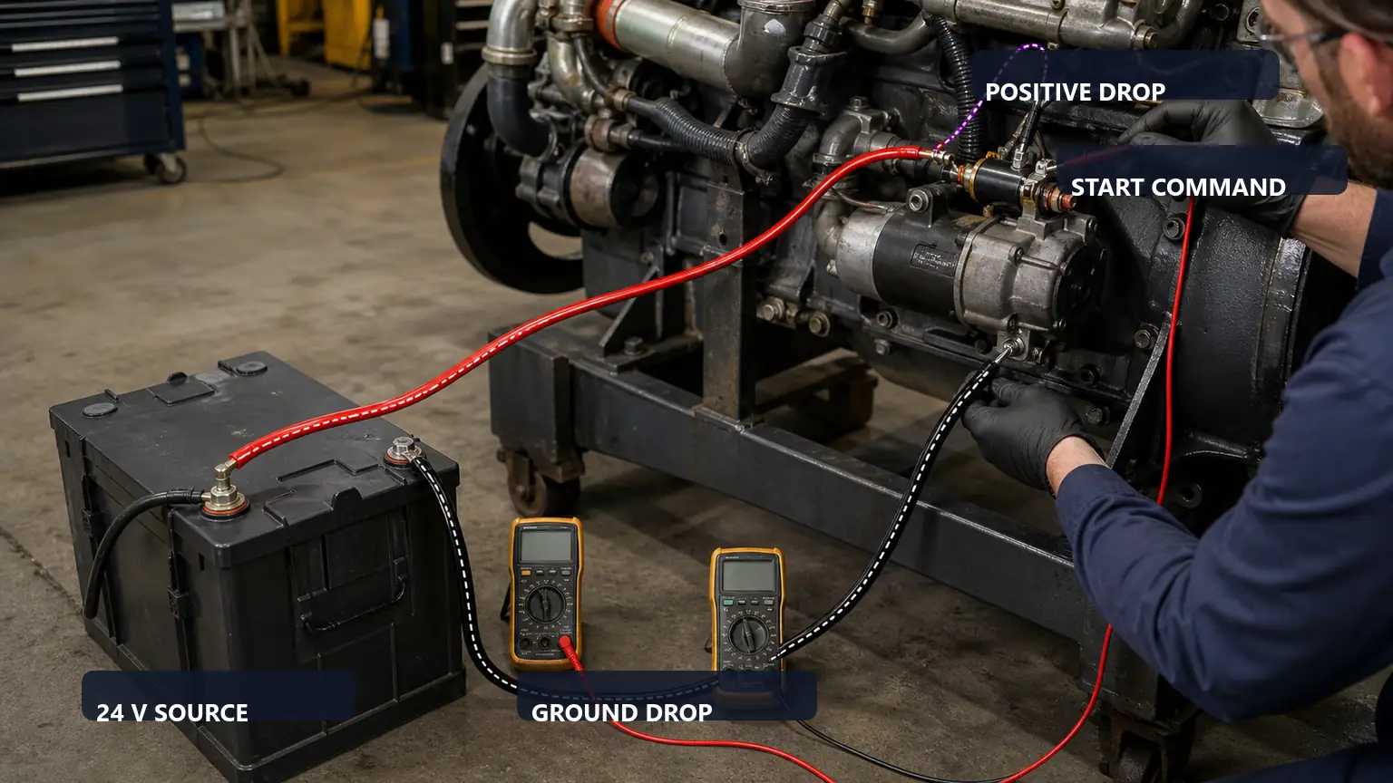
Record the complaint before disconnecting the starter: cold or hot condition, engine speed during the event, battery state, ambient temperature, recent repairs and whether the symptom is a click, slow rotation, intermittent rotation or no response. Inspect the battery, positive path, ground path, control circuit and mounting. A brush repair performed before this baseline can hide the real cause and create an unprovable warranty decision.
Observed pattern | Evidence to collect first | Brush conclusion |
|---|---|---|
Single click with no motor rotation | Battery under load, positive and ground voltage drop, solenoid contacts and motor current path | Possible, not confirmed |
Slow crank at acceptable battery voltage | Cable losses, current draw, engine mechanical load, bushing drag and internal motor condition | Inspect only after external causes |
Intermittent operation that changes with heat or position | Control voltage, connections, brush movement, springs, commutator and armature support | Brush or holder fault is plausible |
Abnormal noise or pinion complaint | Drive, ring gear, nose housing, bushings and alignment | Do not treat as brush-only |
Voltage-drop testing separates vehicle-circuit loss from an internal starter problem. Values and test conditions must follow the applicable service procedure.
Isolate power and follow the approved removal procedure. Preserve the label, reference, mounting orientation and wiring record. Before cleaning anything, photograph brush dust, heat marks, loose hardware, oil or coolant entry and the position of flexible leads. Contamination patterns can be diagnostic evidence; removing them too early weakens the failure record.
Measure every brush at the defined datum and compare the wear pattern. One short, chipped or burned brush can indicate a sticking holder, weak spring, damaged lead or uneven commutator rather than uniform service wear. Record the measurements and the stated service limit instead of reporting only “worn brushes.”
Each brush should move freely through its working range without binding. Inspect the holder for distortion, cracked insulation, conductive debris, corrosion and heat damage. Check that leads are flexible and routed without tension or contact with rotating parts. A new brush installed in a damaged holder is not a complete repair.
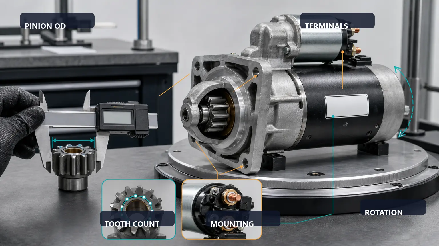
Preserve unit identity and interface evidence before dismantling or quoting repair parts. The staged image provides no approved measurements.
The commutator is the contact surface for the brushes. Inspect for deep grooves, heavy burning, raised bars, contamination, loose segments, eccentricity and evidence of overheating. Cleaning or machining is acceptable only when the starter manufacturer permits it and the finished dimensions and surface meet the stated limits. Do not fit new brushes to a non-serviceable commutator.
Check bushings or bearings and armature support because radial movement can change brush contact and create drag. Evaluate the armature and field circuit with the approved electrical tests. If windings, insulation, the commutator, shaft or housing are damaged, a brush set alone cannot restore a reliable starter.
Repair path | Use when | Reject when |
|---|---|---|
Brush-only repair | Holder, springs, leads, commutator, armature, bushings and drive remain within limits | Heat, contamination or mechanical damage extends beyond the brushes |
Brush-holder or rebuild package | Several related wear items require controlled replacement and the core is serviceable | Kit identity or included parts cannot be verified |
Complete starter replacement | Core damage, downtime risk or lack of controlled rebuild testing makes repair uncertain | Replacement identity and fitment remain unverified |
For replacement decisions, retain the starter reference, voltage, power class where specified, rotation, mounting, pinion tooth count and pitch, drive position, terminals, solenoid clocking and application information. The heavy-duty starter identification guide explains how to build that record.
Assemble with the approved components, cleanliness controls, lubrication locations and torque values. Confirm free movement before energizing. Use a guarded starter test fixture, correctly rated cabling and a documented duty cycle. Record supply voltage, current, speed or torque where the equipment supports it, solenoid action and unusual noise. An unsupported starter must never be energized loose on a bench.
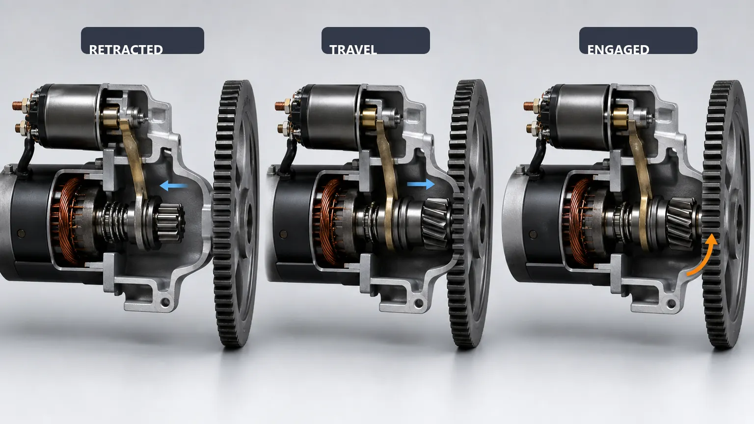
Brush performance and pinion engagement are separate release checks. The image is educational and does not replace an application drawing.
Correct battery, cable, ground, mounting and ring-gear issues before installation. Protect terminals, route cables away from heat and movement, and use the specified fasteners and torque. Repeat the original complaint condition and record cranking behavior and circuit voltage drop. If the repaired starter still draws abnormal current or cranks slowly, stop and reopen the diagnosis instead of attributing the result to brush seating without evidence.
Starter and application references with label photographs
Brush dimensions, material designation, lead length, terminal style and quantity per unit
Holder and spring configuration, included hardware and declared starter-family coverage
Sample inspection method, batch identification, packaging and change-notification process
Warranty evidence required for premature wear or dimensional mismatch
Buyers can review the heavy-duty starter motor range and send the measured unit identity, application and repair scope through the contact page for a matched quotation.
Yes, loss of stable contact can create intermittent operation, but control-circuit, connection, solenoid and armature faults can create the same symptom. Confirm the whole circuit before dismantling.
A change after vibration may suggest an internal contact problem, but it is not a repair and does not identify the failed part. Preserve the observation and continue with controlled tests.
Only if the applicable service procedure permits reconditioning and the finished commutator meets its limits. Deep damage, eccentricity or heat injury can require a wider rebuild or replacement.