ELECDURA NETWORK

Your Whole New Supply Chain For Heavy-Duty Parts
Whatsapp:
+86 18915027366
Phone:
+86 18915027366
Views: 0 Author: Site Editor Publish Time: 2026-06-27 Origin: Site
A turbo actuator symptom does not identify the failed part. Low power, slow boost response, overboost, warning lamps or an actuator-position code can come from the control circuit, air or exhaust path, fuel system, turbo mechanism, actuator or calibration. Replacing the actuator before separating those causes can leave the original fault in place.
Start by identifying the installed turbo mechanism and control type, then collect evidence under the conditions that produced the complaint. This guide helps heavy-duty service and purchasing teams define the repair and replacement enquiry; the engine and turbo manufacturer's current procedure supplies the exact tests, tooling, limits and safety requirements.
Record the complaint before clearing faults or disturbing the linkage. Note whether it occurs at cold start, warm idle, acceleration, high load, engine braking, altitude, regeneration or after a repair. Capture active and stored codes, freeze-frame data, applicable commanded and actual position, boost or manifold pressure, exhaust information and any derate state.
Garrett's system-diagnostics guidance keeps the engine's other systems in scope. A restricted intake, leaking charge-air hose, exhaust restriction, control-supply fault or binding turbo mechanism can create an actuator-like complaint. Use the vehicle maker's diagnostic method rather than attempting to reproduce a dangerous fault by trial and error.
A wastegate controls an exhaust bypass; variable geometry controls a nozzle or vane mechanism. Pneumatic and electronic describe how that mechanism is actuated, not which mechanism the turbo uses. Garrett's explanation of turbo types describes different actuation methods for wastegate and variable-nozzle designs. Confirm the installed arrangement from the complete turbo reference and service information.
Record the bypass-valve arrangement and its specified control system. Do not label the complaint “sticking VGT vanes” merely because the actuator has an external rod. The relevant mechanism, permitted test and replacement part must follow the wastegate unit's own service information.
Distinguish a control fault from resistance in the applicable vane or nozzle mechanism. The VGT illustrations below belong to this branch; they do not depict every wastegate design. Interpret position values using the relevant controller's definitions, not a percentage copied from another application.
Identify the control type first. Check the specified electrical supply and signal path, or the pneumatic supply, hoses and control valve. Communication checks apply only where the design uses them. No response alone does not prove that the actuator motor, electronics or pneumatic element has failed.
Collect scan data under the specified test conditions and review linkage movement, the relevant mechanism and calibration status. A position deviation is not automatically a failed position sensor; the command, feedback and mechanical response must be interpreted together.
Check charge-air leaks, intake or exhaust restrictions, harness condition and the operating conditions that trigger the complaint. An intermittent symptom does not establish that the turbo is worn or undersized.
Review command history, the correct controlled mechanism, the exhaust path and any application-specific braking controls. Do not assume that fitting an actuator will correct mechanical binding or a fault elsewhere in the braking system.
Check installed references, connectors, linkage, the installation record and required calibration or learned values. “New” describes condition, not proof that a part is configured correctly for every application.
Use the correct wiring diagram to identify supply, ground, communication and any separate sensor circuits. Inspect for water, corrosion, heat damage, spread terminals, cable strain and previous repairs. Do not apply power or back-probe until the approved method and pin functions are known.
A no-load voltage reading may miss resistance in a connection. Where the manufacturer's procedure calls for it, record circuit behavior under the specified condition alongside command and feedback. Resolve a supply, wiring or communication defect before concluding that the actuator cannot respond. Preserve connector seals and use suitable probes.
Identify whether the specified source is pressure or vacuum, then locate the hoses and control valve in the service diagram. Some pneumatic arrangements also have electrical position feedback, so a connector does not by itself identify an electric drive motor. Do not transfer test connections or limits from another actuator family.
Garrett's installation guidance includes the hoses between the control valve and pneumatic VNT actuator in the checks. Follow the exact application's method to examine routing, condition, connections and delivered control supply. A hose or control-valve fault changes the repair boundary; changing the actuator alone does not establish that the control path is sound.
Perform pressure, vacuum or movement tests only when permitted, using the specified limits and equipment. There is no universal opening pressure, stroke, rod length or stop setting in this guide. Obtain the correct procedure before using a hand pump or another external source on an unfamiliar unit.
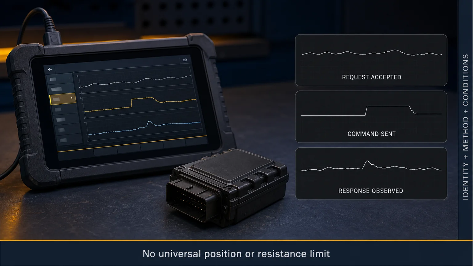
Illustrative VGT command-and-response review. The graphic is not an engine-specific diagnostic result or an acceptance limit.
Do not force the lever or disturb a calibrated linkage. Use the manufacturer's isolation procedure only where separate testing is permitted. For variable geometry, the mechanical question concerns approved vane or nozzle travel; for a wastegate, it concerns the bypass-valve mechanism. Record which mechanism was actually checked.
Garrett warns that its electronic actuator gears are self-blocking and that forcing the operating arm or rod can break them. Establish the permitted isolation method before interpreting hand resistance as a seized turbo mechanism; this warning is not permission to force another design.
Where an approved check confirms binding, investigate contamination, corrosion, damage or another relevant cause instead of fitting a new actuator to the unresolved mechanism. Conversely, permitted movement does not by itself prove correct calibration or successful control under the original complaint conditions.
Inspect the intake and charge-air path for restrictions, loose clamps, split hoses, damaged coolers and leaks. Check the exhaust path according to the application. Review fuel-delivery or combustion evidence when smoke or low power does not follow actuator command, and verify relevant engine-sensor readings before treating them as established conditions.
Oil leakage or turbo noise also requires system review. Check oil feed and drain condition, crankcase pressure, intake cleanliness and installation history. An actuator cannot correct an oil-supply or blocked-drain problem. The turbocharger installation and oil-path guide covers related release checks after a turbo change.
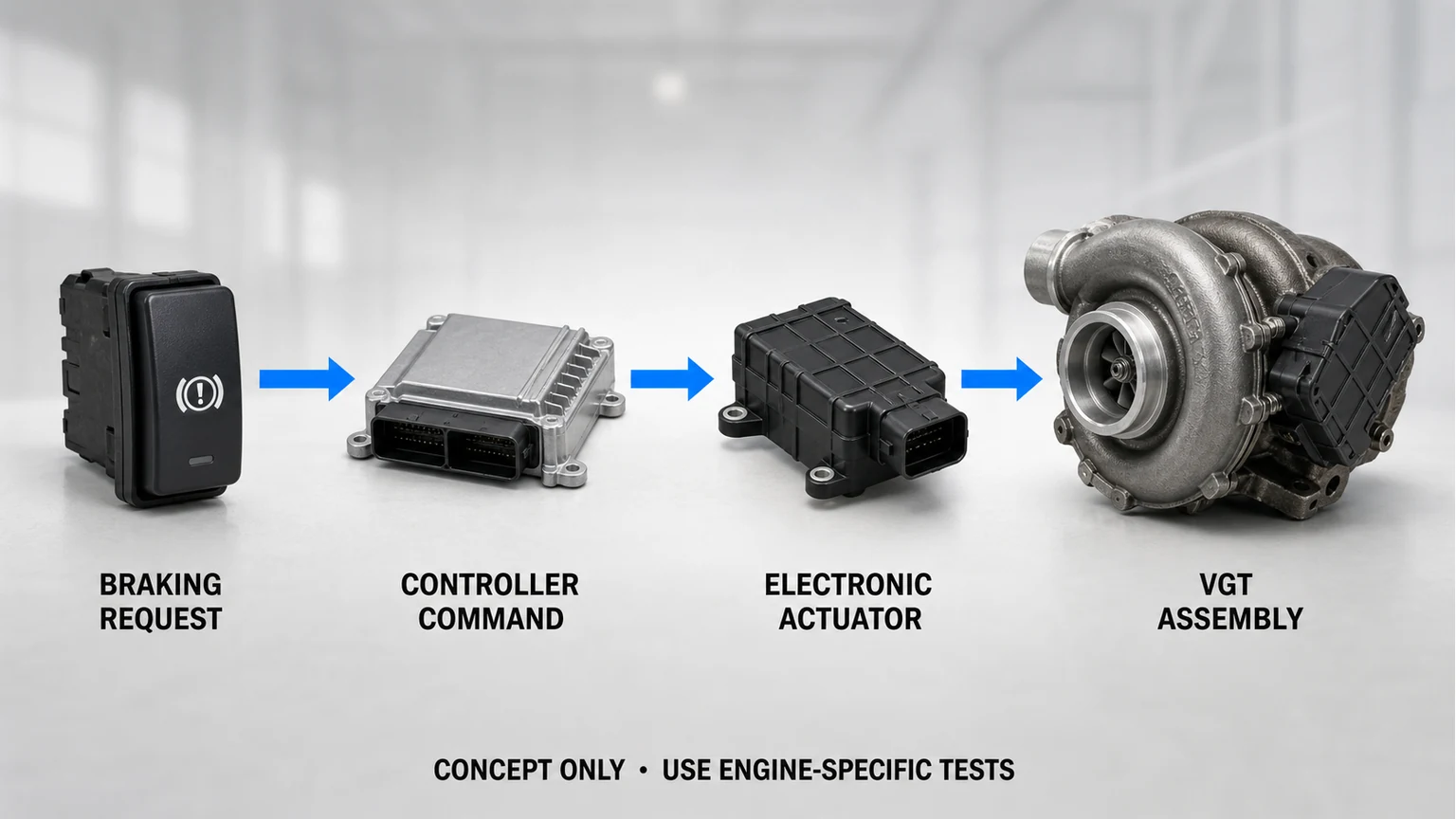
Conceptual VGT control chain. The actuator is one link; this is not an application-specific pinout or a diagram of every engine-braking system.
When the relevant turbo mechanism passes its approved check, correct the identified electrical supply, wiring, hose or control-valve defect. Verify control delivery and response afterward. Replace the actuator only if its own failure is separately established.
If the turbo mechanism and related systems pass, the actuator may be the service boundary where separate replacement is permitted. Release still requires the correct reference, approved installation or linkage sequence, required calibration and post-repair evidence.
Follow the approved service policy for the vane/nozzle or wastegate mechanism and turbo assembly. Correct the underlying cause and complete the applicable oil, air, exhaust and installation checks. A new actuator should not be used to conceal unresolved mechanical resistance.
Correct a confirmed air, exhaust, fuel or sensor fault, then repeat the approved test for the original complaint. If records conflict or the required procedure is unavailable, hold the part decision and obtain application-specific support. Neither a forced linkage setting nor a generic calibration resolves missing evidence.
Provide the complete turbo and actuator references, engine/equipment identity, applicable serial range, connector photos, linkage style, control type and fault evidence. For electrical designs, identify the specified electrical configuration; for pneumatic designs, identify the documented control arrangement. Include the mechanism-inspection result rather than selecting a part by a similar connector or housing.
State whether the request concerns a complete turbocharger, actuator, cartridge or another service part. Ask for the supplied condition, installation instructions, interchange basis and any supersession conditions. Establish which calibration or programming, if any, is required, where it is performed and which approved tool or service route is needed. Do not treat “calibrated” as a complete description without its application and scope.
Follow the approved mounting, linkage and calibration sequence. Record installed references, the applicable tool/software procedure, required learned or calibrated status, fault-code outcome and available command-versus-response evidence. Check for leaks, abnormal noise and wiring or hose contact with hot or moving parts.
Confirm the result under the original complaint conditions using the prescribed safe test. Clearing a code or observing one successful movement is not the same as demonstrating that an intermittent complaint has been resolved.
Conceptual VGT repair boundaries. The graphic does not replace the service policy or calibration procedure for the installed unit.
Use the heavy-duty turbocharger category for orientation. For part support, send Elecdura the application, turbo and actuator labels, connector images, fault details and required quantity. Identify the unresolved matching question, including the mechanism and control type. Keep any proposed replacement conditional until its repair boundary, interchange and installation path are established.