ELECDURA NETWORK

Your Whole New Supply Chain For Heavy-Duty Parts
Whatsapp:
+86 18915027366
Phone:
+86 18915027366
Views: 0 Author: Site Editor Publish Time: 2026-07-23 Origin: Site


A blower motor resistor controls fan speed in HVAC systems that use stepped resistance to regulate the blower motor. When it fails, some fan speeds may stop working, but the symptom alone does not prove the resistor is defective. A worn blower motor, overheated connector, damaged wiring, poor ground or failed electronic control module can produce similar problems. Diagnosis should begin by identifying the control design and recording which speeds operate. With the circuit safely isolated, inspect the resistor and connector; then use the vehicle-specific procedure to check circuit voltage drop and blower motor current under load. Confirm the root cause before selecting a replacement.
A blower motor resistor regulates fan speed in HVAC systems that use a resistor pack and discrete speed settings. In a conventional arrangement, different resistance paths limit the current supplied to the blower motor, producing different fan speeds. The highest speed may use a separate circuit that bypasses some or all of the resistor elements, depending on the design.
That arrangement explains why a failed resistor pack can cause certain speed settings to disappear while another setting still works. However, not every HVAC system uses this design. Some vehicles use an electronic blower motor control module that varies motor operation through electronic control rather than relying on a conventional stepped resistor pack.
Before testing, identify which component is installed. A resistor pack may contain multiple resistance paths and a thermal protection device. An electronic module may instead contain semiconductor components, power electronics and a control circuit. Their connector layouts, test methods and failure patterns are not interchangeable.
Do not judge an electronic module by checking resistance across arbitrary terminals. Use the correct wiring diagram and service procedure to identify its power supply, ground, control input and motor output.
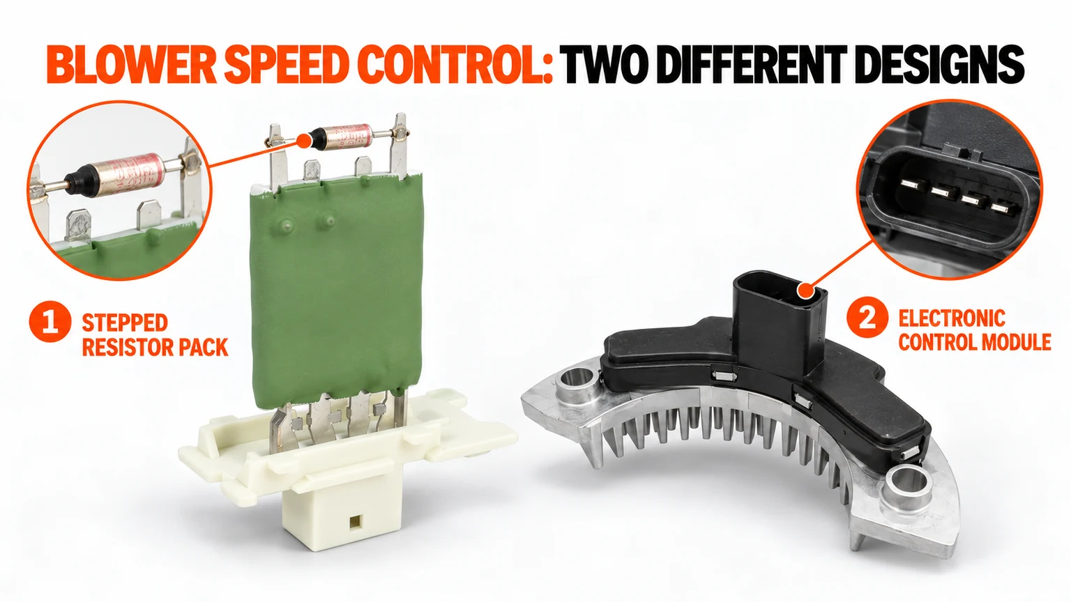
The operating pattern can help narrow the diagnosis, but each symptom has more than one possible cause.
Observed symptom | Possible causes | What to check next |
|---|---|---|
Only some fan speeds work | Failed resistor element, damaged connection, speed switch or control-circuit fault | Confirm the control design and check the affected circuit paths. |
Blower operates only at high speed | Failed lower-speed resistor paths, a relay or switch fault, or a wiring problem, depending on the circuit | Compare the actual circuit with the vehicle wiring diagram before condemning the resistor. |
Blower does not operate at any speed | Loss of power, fuse or relay fault, failed motor, poor ground, control fault or damaged wiring | Verify the power and ground paths, command signal where applicable, and motor condition. |
Blower runs intermittently | Loose terminals, heat-damaged connectors, wiring faults, motor wear or an intermittent control fault | Inspect connector tension and wiring, and reproduce the complaint using an approved procedure. |
Blower continues running after shutdown | Control-module, relay, switch or circuit faults, depending on the vehicle design | Check the shutdown logic and circuit diagram instead of assuming the resistor is responsible. |
A complaint such as “only high speed works” is a useful diagnostic clue, not a universal failure test. Some resistor-controlled systems use a separate high-speed circuit, but the exact arrangement varies. Electronic control systems can show different symptoms.
Start with the vehicle wiring diagram and identify the installed component. Before disconnecting or measuring anything, follow the applicable isolation procedure and allow hot components to cool. Never measure resistance on an energized circuit.
With the system operated according to the vehicle's service procedure, record which fan settings work and whether the symptom changes with temperature, vibration or operating time. Listen for unusual blower noise and note any evidence of restricted airflow.
Record the exact complaint before removing the component. This helps distinguish a speed-control fault from a blower motor that is failing intermittently or drawing excessive current.
After safely isolating the circuit, inspect the resistor pack, module connector and harness for discoloration, melted plastic, corrosion, loose terminals, water intrusion or damaged insulation.
Heat damage at the connector matters even if the resistor itself looks intact. A loose or high-resistance connection can create localized heating and voltage loss, and replacing only the resistor may leave the original problem unresolved.
For a conventional resistor pack, use the wiring diagram and manufacturer procedure to identify the correct terminals and specified test conditions. Measure only with the circuit de-energized and the component isolated as required. Compare the results with the specification for that exact part and vehicle.
Do not apply a generic resistance value to every blower resistor. The number of stages, resistance values, thermal protection and circuit arrangement vary. An open circuit in a specified resistor path may indicate a failed element, but the result must be interpreted against the correct diagram.
Resistance measurements are not an appropriate stand-alone test for an electronic control module. Its power supply, ground, command input and output need to be evaluated using the specified diagnostic method.
A circuit can appear satisfactory during an unloaded check yet develop excessive voltage loss when the blower is running. Where the service procedure permits, measure voltage at the relevant circuit points while the system operates under the specified conditions.
Use the correct wiring diagram to locate the supply, ground, connectors and control paths. A voltage-drop result must be interpreted in the context of the actual circuit and its manufacturer limits. Do not use a universal threshold for every heavy-duty truck or transfer a value from a different voltage system.
Standard’s blower motor control guidance identifies excessive motor current, heat and water damage as concerns for control components and connectors. Its vehicle examples do not establish a common current limit or fault pattern for all heavy-duty trucks.
A replacement resistor or control module can fail again if the blower motor draws excessive current or the assembly cannot dissipate heat as designed. For this reason, diagnosis should include the motor and the airflow conditions around the control component.
Use a suitable current clamp and follow the vehicle-specific test method. Compare the observed current with the specification for the installed motor and operating condition. An elevated reading may indicate a motor problem or another source of excessive load, but it should not be interpreted without the correct reference data.
Do not apply a current limit taken from an unrelated light-duty vehicle or a different motor. Voltage, motor design, airflow restriction and operating conditions can all affect the result.
Many blower resistors and electronic control modules rely on their designed mounting position and surrounding HVAC airflow to manage heat. Check for blocked ducts, debris, water intrusion, incorrect installation and missing or damaged mounting features.
Some electronic modules can overheat if energized outside their specified installation and cooling conditions. Do not run a module for an extended period while it is removed from its intended airflow path unless the manufacturer's procedure explicitly permits that test.
If a connector has melted or discolored, inspect the corresponding terminals and harness rather than replacing the damaged plastic alone. Confirm that the replacement connector, terminal arrangement and wire condition meet the applicable service requirements.
Do not bypass a thermal fuse or other protective device to restore operation. The protection may be responding to a genuine overheating condition that still needs to be identified.
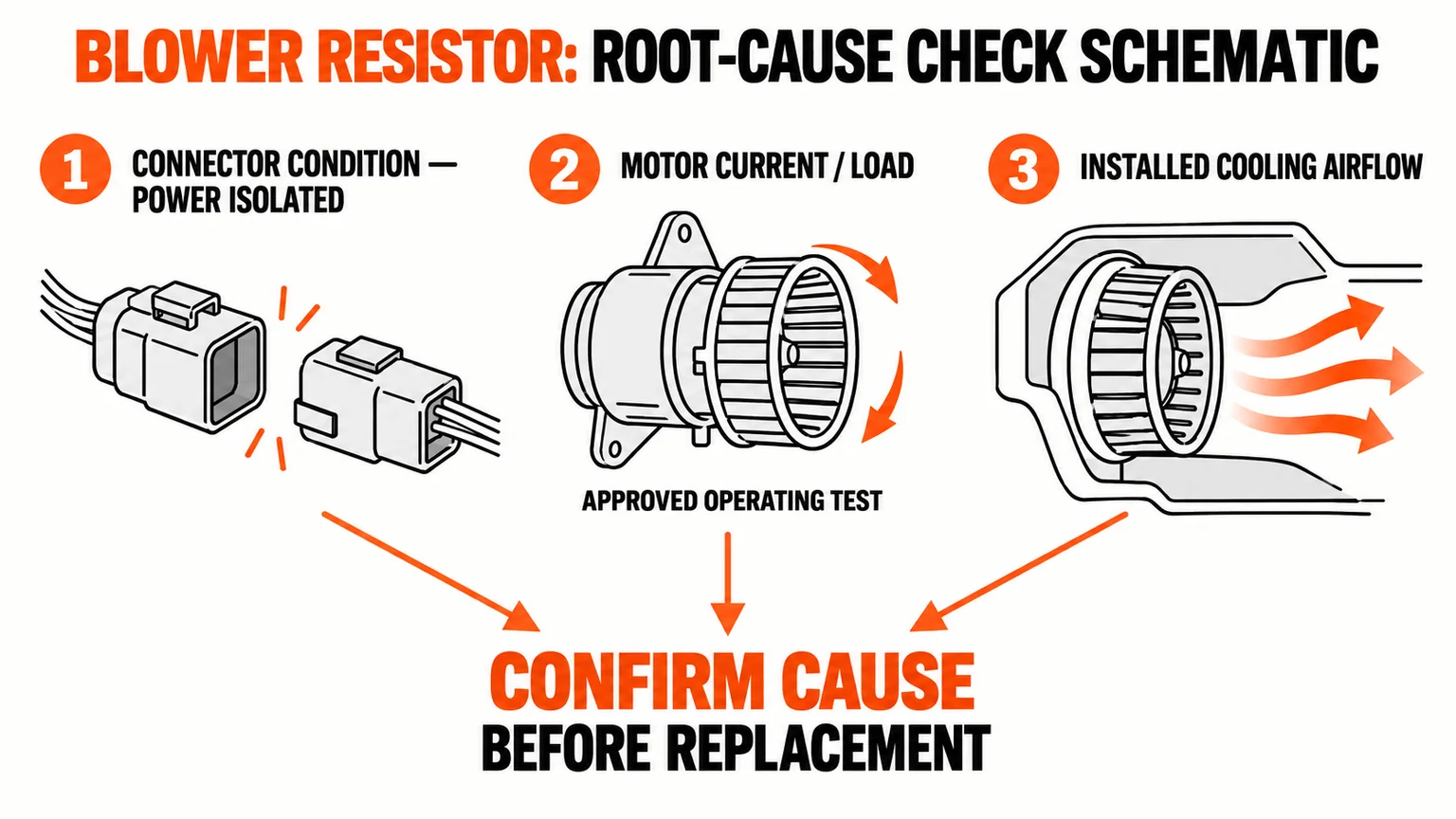
A blower motor resistor should be matched to the original application, not selected solely by appearance or a broad product description. A visually similar part may have a different voltage rating, terminal arrangement, resistor-stage configuration or mounting design.
Part number: Record the number on the removed component and any verified reference numbers.
System voltage: Confirm the vehicle's specified electrical system and the replacement's intended application.
Control type: Distinguish a conventional resistor pack from an electronic blower motor control module.
Connector: Check pin count, terminal positions, connector keying and harness compatibility.
Mounting: Compare mounting points, insertion depth and the designed position within the HVAC housing.
Vehicle application: Provide make, model, model year where available, and the relevant HVAC configuration.
Condition and reference evidence: Supply clear photographs of the label, connector, mounting features and both sides of the original part.
For example, Elecdura lists a specific 24V blower resistor reference for Volkswagen Constellation and Titan applications. That page is a reference for the identified product and does not establish compatibility with other trucks or all 24V systems.
For importers, distributors and fleet-parts buyers, an accurate enquiry should combine the product reference with evidence from the installed component. This helps separate a confirmed fitment request from an unresolved diagnosis.
Include the following information where available:
Original part number or reference marking.
Vehicle model, production year and HVAC application.
System voltage and control type.
Connector photographs, pin layout and mounting details.
Observed fan-speed symptoms and any completed diagnostic checks.
Required order quantity, destination market and expected repeat demand.
Packaging, labeling and product-identification requirements.
Keep the technical question separate from the commercial quotation. If the control design or part reference is uncertain, state which information is missing rather than assuming that a similar-looking component is interchangeable.
In an HVAC system that uses stepped resistance, it helps regulate blower motor speed by changing the resistance in the relevant circuit paths. Some systems use electronic control modules instead, so the correct diagnosis depends on the installed design.
Identify the circuit and component first. Inspect the connector and wiring, then use the manufacturer's procedure to measure resistance on a safely isolated conventional resistor pack. If necessary, check voltage drop under load and investigate motor current. Do not use resistance measurements alone to assess an electronic control module.
On some resistor-controlled systems, the high-speed circuit bypasses the lower-speed resistor paths, so a failed resistor path is one possible cause. A switch, relay, connector or wiring fault can create a similar symptom. Confirm the actual circuit design before replacing a part.
It can contribute to repeat failure if the motor draws excessive current or the assembly operates outside its designed thermal conditions. Check motor current, connector condition, mounting and airflow before approving the replacement.
Do not improvise a bypass or defeat thermal protection. Such a test can create excessive current, damage wiring or expose the circuit to unsafe conditions. Use the vehicle manufacturer's approved diagnostic procedure and suitable test equipment.
Do not assume they are interchangeable. Verify the intended system voltage, circuit design, connector and vehicle application against the part reference and service information. A similar appearance or matching connector does not establish electrical compatibility.
Send the original part number, vehicle and HVAC details, system voltage, clear photographs of the connector and mounting features, and the required quantity. Include the observed fan-speed pattern and any completed electrical checks so the enquiry can distinguish a confirmed replacement requirement from an unresolved circuit fault.
Elecdura supports wholesale enquiries for heavy-duty aftermarket parts. The specific application and commercial terms must be reviewed before compatibility is confirmed. For a sourcing enquiry, submit your details through the Elecdura contact page.


