ELECDURA NETWORK

Your Whole New Supply Chain For Heavy-Duty Parts
Whatsapp:
+86 18915027366
Phone:
+86 18915027366
Views: 0 Author: Site Editor Publish Time: 2026-07-22 Origin: Site
Replacing a heavy-duty truck alternator involves more than matching a part number and installing a unit that fits the mounting bracket. The replacement must also match the vehicle’s electrical system, pulley geometry, mounting arrangement, terminal functions, and control strategy.
A replacement that looks correct may still cause charging problems if its connector, belt alignment, or voltage-sensing arrangement differs from the original. For fleet maintenance teams, repair shops, importers, and distributors, a consistent fitment and commissioning process helps reduce avoidable installation errors, repeat work, and incorrect parts orders.
This guide explains how to prepare for alternator replacement, verify compatibility, inspect the installation, and document the results. Detailed procedures and acceptance limits must follow the applicable vehicle and alternator manufacturer’s service instructions.
If the failed component has not been confirmed, start with alternator symptom diagnosis before selecting a replacement.
An alternator should not be condemned solely because a battery is discharged or a charging warning appears. Battery condition, drive-belt problems, poor grounding, damaged cables, and control-circuit faults can produce similar symptoms.
Before approving a replacement, technicians should establish whether the alternator itself has failed or whether another part of the charging system is responsible.
A practical decision sequence is:
Record the reported symptoms and any charging-system fault codes.
Inspect the battery bank, drive belt, tensioner, pulleys, mounting hardware, and electrical connections.
Test battery condition and charging-circuit integrity using the applicable service procedure.
Evaluate alternator output under the specified test conditions.
Replace the unit when test results and manufacturer procedures support that decision.
If the alternator passes its required tests, investigate the remaining system rather than replacing it automatically. If the cause is confirmed, record the failure and correct any underlying installation or electrical issue before fitting the replacement.
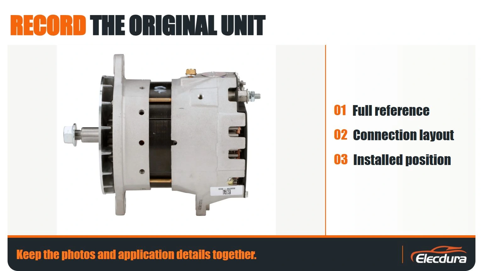
The original unit provides valuable fitment evidence. Capture its identification label and installation interfaces before disconnecting or removing it.
Record the following information:
Original part number and any identifiable OE reference.
Vehicle make, model, year or build information, and engine application.
System voltage and the original alternator’s rated output.
Mounting style, pivot dimensions, mounting-ear spacing, and adjustment arrangement.
Pulley type, groove count, diameter, and belt-plane offset.
Electrical connector shape, terminal positions, and documented terminal functions.
Ground arrangement and any remote-sensing or communication connections.
Fan and housing clearance, cable routing, and nearby brackets.
Photographs should show the label, mounting points, pulley, connector, main output terminal, and cable routing. These records help distinguish products that share a broad application description but have different physical or electrical interfaces.
Important: A matching reference number is useful evidence, but it should not replace application verification. Where the label, catalog data, and physical installation disagree, resolve the discrepancy before ordering.
Keep the photos and application details together.
A reliable replacement check covers several interfaces together rather than relying on nominal voltage or external appearance alone.
Fitment item | What to verify | Why it matters |
|---|---|---|
Application reference | Original part number, OE reference, and engine or vehicle details | Reduces the risk of selecting an incorrect application |
Electrical system | System voltage, rated output, and regulator requirements | Confirms that the replacement is appropriate for the intended system |
Mounting | Bracket design, pivot dimensions, bolt positions, and adjustment points | Prevents mounting and clearance problems |
Pulley and belt | Groove profile, groove count, diameter, offset, and alignment | Helps avoid belt tracking problems and abnormal mechanical loading |
Connector and terminals | Connector keying, pin assignments, terminal functions, and polarity | Prevents incorrect connections and control-system incompatibility |
Ground and sensing | Ground path, remote-sense connection, and applicable control wiring | Helps maintain correct regulation and charging performance |
Physical clearance | Housing, fan, hoses, wiring, brackets, and engine movement | Reduces interference and potential damage |
Some alternators use a remote-sense lead to monitor voltage at a designated point in the electrical system. Others use different regulation or control arrangements. The replacement must be compatible with the vehicle’s actual configuration.
A connector that physically plugs in is not necessarily electrically equivalent. Identify terminal functions from the applicable wiring diagram and product documentation; never assume that similarly positioned pins perform the same function.
For example, Delco Remy publishes model-specific instructions for heavy-duty alternators and remote-sensing configurations. Those instructions demonstrate why installation details must be checked against the particular design, rather than generalized across all alternators. Delco Remy alternator installation and service instructions.
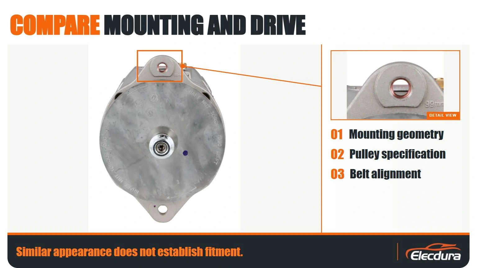
Similar appearance does not establish fitment.
Before removing the original alternator, follow the vehicle manufacturer’s procedure for isolating electrical power. Heavy-duty vehicles may have multiple batteries, auxiliary power sources, or automatic-start systems.
The alternator output terminal can remain electrically hazardous when connected to a battery. Never treat it as safe merely because the engine is stopped. Use the specified isolation procedure and appropriate protective equipment.
After removal, inspect the surrounding system rather than treating the alternator as an isolated component.
Drive system: Check the belt, tensioner, idlers, pulley condition, alignment, mounting brackets, and evidence of abnormal belt wear. A damaged pulley or poorly functioning tensioner may contribute to repeat problems.
Electrical connections: Inspect the main output cable, ground connections, battery interconnects, connectors, protective devices, and wiring insulation. Look for corrosion, looseness, heat damage, abrasion, or contamination.
Operating environment: Check for oil or coolant contamination, restricted clearance, excessive vibration, and other conditions that could affect the replacement.
Correct identified faults before installing the new unit. Otherwise, the original failure mechanism may remain in place.
Compare the replacement and original units side by side before installation. Confirm that the mounting arrangement, pulley, connector, terminal locations, and housing clearances match the approved application.
During installation:
Use the specified mounting hardware and tightening procedure.
Confirm that brackets and support braces are correctly installed.
Verify pulley alignment and belt routing using the prescribed method.
Route cables away from moving components and excessive heat.
Ensure that electrical terminals are clean, secure, and protected as specified.
Reconnect ground, output, sensing, and control connections according to the applicable wiring diagram.
Do not transfer an old pulley, spacer, fan, or other component unless the replacement instructions explicitly permit it. Do not apply a universal torque value: tightening requirements depend on the particular component and mounting design.
For model-specific installation instructions, use the relevant manufacturer documentation. Delco Remy provides a searchable collection of heavy-duty alternator installation and service sheets. Alternator instruction sheets.
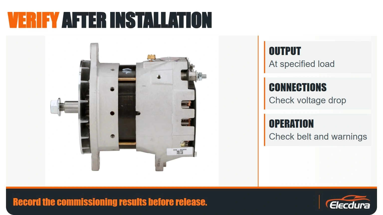
Installation is not complete until the charging system has passed the required post-installation checks.
Verify electrical connections, battery polarity, belt installation, cable routing, terminal protection, and clearance. Remove tools and temporary connections, and confirm that all components are secured.
Start the engine according to the vehicle service procedure. Observe warning indicators, charging-system behavior, belt tracking, and any abnormal noise or smell. Stop the engine if a condition indicates an immediate safety or equipment risk.
Use the specified test procedure to evaluate charging performance under appropriate operating conditions. Where required, compare readings at the alternator, battery bank, and designated voltage-sensing point.
If readings differ unexpectedly, investigate the cable path, grounds, connections, sensing circuit, and test conditions before concluding that the replacement is defective.
Where required by the manufacturer, repeat the relevant checks after the system reaches its prescribed operating temperature. Record the conditions and results, and compare them with the applicable specification.
Do not apply a generic voltage or current threshold to every heavy-duty vehicle. System voltage, battery technology, temperature, alternator design, and electronic regulation strategy can affect the correct acceptance criteria.
For additional reference, Delco Remy publishes a heavy-duty troubleshooting guide covering visual inspection, batteries, belts, pulleys, and electrical connections.
Record the commissioning results before release.
A useful service record should make the installation traceable and help distinguish product issues from vehicle-side faults.
Record the following where applicable:
Original and replacement part references.
Vehicle and engine application.
Battery and charging-system test results.
Identified failure cause and corrective work.
Belt, pulley, mounting, and wiring checks.
Commissioning results under documented test conditions.
Installation date, vehicle mileage or engine hours, and relevant fault codes.
Replacement unit identification, supplier batch, and purchase reference.
For importers and distributors, retain the approved sample details, label photographs, connector images, fitment records, and agreed inspection criteria. These records help purchasing teams verify repeat orders and investigate discrepancies without relying on a shortened part description.
When requesting a replacement for a commercial vehicle application, provide as much of the following as is available:
Original part number or OE reference.
Vehicle, engine, and application details.
Photos of the identification label, mounting points, pulley, and connector.
System voltage and required output, where known.
Required quantity and destination market.
Packaging, labeling, and other purchasing requirements.
If key information is missing or conflicting, request technical confirmation before treating a cross-reference as an approved fitment.
An OE reference is a useful starting point, but it may not resolve every application variation. Confirm the vehicle and engine details, mounting arrangement, pulley, electrical connector, and control configuration before approving the replacement.
Yes. Voltage alone does not establish compatibility. Differences in rated output, mounting, pulley geometry, terminal assignments, sensing arrangements, or physical clearance can prevent a replacement from working correctly.
Yes. The belt drive, mounting hardware, cables, grounds, and control connections can contribute to charging problems or damage a replacement. Inspect them during the replacement process and correct any identified faults.
Follow the vehicle and alternator manufacturer’s commissioning procedure. This may include pre-start checks, initial operation, controlled-load testing, voltage-drop checks, and hot-condition verification. Use model-specific acceptance criteria rather than universal thresholds.
Provide the original reference, application details, label and interface photos, required quantity, and packaging requirements. Additional information about voltage, output, and connector functions can help resolve ambiguity before an order is placed.
A successful heavy-duty alternator replacement requires verified fitment, correction of the original failure cause, controlled installation, and documented commissioning. A familiar part number or matching voltage is not enough when mounting, pulley, wiring, and control interfaces may differ.
For fleet operators and repair businesses, a repeatable process improves installation records and helps prevent avoidable rework. For importers and distributors, complete application evidence makes replacement-part sourcing more precise and supports better control of repeat orders.
For a replacement quotation, send Elecdura the alternator label, mounting and connector photographs together with the application and test findings. Resolve any mismatch before approving the order.