Your Whole New Supply Chain For Heavy-Duty Parts
Whatsapp:
+86 18915027366
Phone:
+86 18915027366
Views: 0 Author: Site Editor Publish Time: 2026-07-28 Origin: Site
Alternator overcharging is less common than low output, but it can damage batteries, lamps, control modules, telematics, refrigeration electronics, and trailer systems before a fleet recognizes the pattern. A dashboard reading above normal is only the beginning of the diagnosis. Temperature compensation, battery state, remote-sense wiring, poor grounds, regulator control, and the measuring point all influence the voltage a technician sees.
For commercial trucks and off-highway equipment, the repair decision should protect the entire charging network rather than focus on a single component. The Elecdurauto heavy-duty alternator range provides reference-level options for importers and fleet buyers, yet no replacement should be selected until voltage is measured at the battery posts, alternator output terminal, and sense circuit under controlled conditions.
This guide explains how to confirm a genuine overcharge, separate regulator behavior from wiring faults, evaluate battery consequences, and prepare an evidence-based B2B sourcing file. It is intended for fleet technicians, repair networks, distributors, and importers who need a repeatable method that prevents a second alternator from being blamed for an unresolved vehicle-side condition.
A single voltage threshold cannot describe every heavy-duty charging system. Cold batteries may receive a temporarily higher set point, while hot batteries require less charging voltage. Some engine controllers also raise or lower the target according to battery temperature, electrical demand, state of charge, regenerative strategy, or idle-management logic. Record ambient temperature, battery temperature, engine speed, and active loads with every reading.
Confirm the instrument before diagnosing the vehicle. Compare the workshop meter with a known reference or a second meter, connect directly to clean battery posts, and observe voltage from key-on through crank, idle, governed speed, and load changes. A scan-tool target voltage is useful only when it is compared with the voltage actually reaching the battery.
For a distributor or fleet buyer, the definition of overcharging should identify duration as well as peak value. A brief cold-start rise has different consequences from sustained high voltage during a highway route. The purchasing record should state the system voltage, normal target range from service information, maximum observed reading, temperature, duty cycle, and how long the condition persisted.
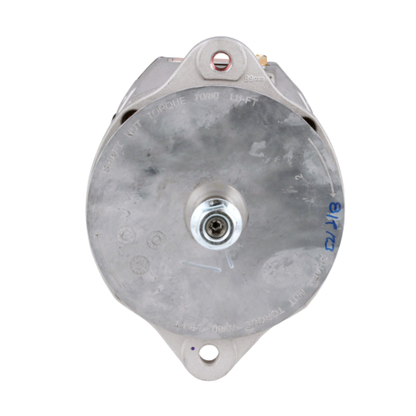
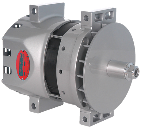
A heavy-duty alternator reference for comparing system voltage, mount, regulator, and terminal configuration.
Battery-post voltage before starting and after surface charge dissipates
Charging voltage at idle, working speed, and highest normal electrical load
Battery or ambient temperature used by the control strategy
Scan-tool target voltage and actual measured voltage where available
Do not classify an alternator as overcharging until elevated voltage is reproduced with a verified meter and the temperature-compensated target is understood. A B2B claim should include the time trace, not only the highest photographed number.
The alternator output stud and battery positive post should remain close in voltage while current flows. Excessive resistance in the charging cable, isolator, master switch, fuse link, or connection can create a higher alternator-terminal reading even when the battery itself is not receiving excessive voltage. Measure the difference directly across the positive path under load instead of subtracting readings taken at different times.
Ground-side resistance can create equally misleading results. Place the meter between the alternator case and battery negative post while the system carries a representative load. Paint, corrosion, loose brackets, braided strap damage, and engine-to-frame ground faults can shift the regulator reference or overheat connections. A clean static continuity check does not replace a loaded voltage-drop test.
If the alternator terminal is high but battery-post voltage remains controlled, investigate cable loss and sense-wire placement before ordering. If both points are high together, move toward regulator command, remote sensing, and battery feedback. This split prevents parts buyers from treating every high alternator-terminal reading as proof that the replacement unit must use a lower output rating.
Alternator B+ to battery positive voltage drop
Alternator case to battery negative voltage drop
Voltage before and after isolators, switches, and protective links
Connection temperature or discoloration under sustained load
Record cable gauge, terminal condition, route, and measured drop before approving a warranty return. A new heavy-duty alternator cannot correct a corroded high-current path or a regulator reference distorted by a weak ground.
Remote-sense regulators are designed to control voltage at a selected point in the electrical system. An open, high-resistance, or misrouted sense wire can make the regulator believe system voltage is lower than it really is. The alternator may then raise output in an attempt to correct a loss that exists only in the feedback circuit. Consult the vehicle diagram and identify every sense, ignition, lamp, and communication terminal.
Back-probe the sense circuit with the connector installed so the measurement represents operating load. Compare sensed voltage with battery-post voltage while moving the harness and changing major loads. Inspect crimp tension, splice corrosion, repaired sections, connector locks, and any added accessory wiring that may have shifted the sensing point away from the original design.
For replacement matching, connector shape alone is insufficient. Regulators with visually similar plugs may use different terminal functions or communication protocols. When reviewing options such as the 40SI 12V 300A/320A J180 alternator, include terminal labels, wiring photographs, controller strategy, and the original reference so the supplier can confirm the correct control family.
Connector face and wire-color photographs
Sense voltage versus battery-post voltage under changing loads
Harness wiggle-test result and splice inspection
Controller or regulator communication type
Do not approve a visually similar alternator unless sense, ignition, lamp, and data terminals match the vehicle architecture. Wrong regulator logic can create high voltage even when the case and pulley fit perfectly.
A failing regulator may hold normal voltage at idle and lose control at higher speed, after heat soak, or when a large load switches off. Build a controlled test sequence that raises engine speed gradually, applies known loads, removes them one at a time, and continues until the alternator reaches normal operating temperature. Avoid uncontrolled battery disconnection because it can create damaging transients.
Watch for overshoot, delayed recovery, cycling, or a set point that climbs with alternator temperature. Where the engine controller requests voltage, compare command and feedback rather than judging the regulator in isolation. A stable field command with rising actual voltage points in a different direction from an unreasonable commanded target produced by battery-sensor or software inputs.
Heavy-duty fleets should record the exact speed and load at which control is lost. This information helps a repair network reproduce the complaint and helps an importer separate an electrical-control mismatch from a mechanical fitment issue. It also establishes a bench-test profile for sample approval before a larger order.
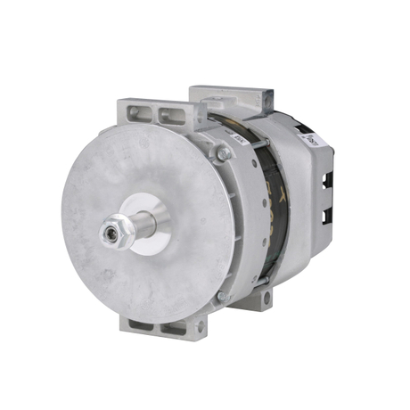
Terminal and case configuration should be matched before a regulated output test is accepted.
Idle-to-working-speed voltage trace
Load application and load-dump recovery without disconnecting batteries
Hot-operating voltage after a representative run
Commanded versus measured voltage on controlled systems
An approved replacement must regulate through speed, load, and temperature transitions without harmful overshoot. The batch test should use the same voltage system and control inputs documented on the fleet application.
A sulphated, internally open, shorted, incorrectly matched, or poorly connected battery bank can change charging behavior. Mixed battery age, capacity, chemistry, or state of charge is especially important on 24V series systems and vehicles with auxiliary banks. Test each battery individually after isolating surface charge and compare conductance, open-circuit voltage, and load response.
Battery temperature sensors, current sensors, and intelligent battery monitors can command inappropriate voltage when calibration, mounting, polarity, or communication is wrong. Inspect sensor placement and scan data, then compare sensor-reported temperature and current with independent observations. Reset or relearn procedures should follow the vehicle manufacturer’s service information after battery work.
Parts buyers should avoid describing battery damage as automatic proof of alternator defect. Bulging cases, electrolyte loss, lamp failures, or module faults support the overcharge history, but root-cause evidence still has to identify regulation or feedback failure. A complete claim includes battery test results before and after the charging correction.
Individual battery age, capacity, chemistry, and state of charge
Series-pair or parallel-bank balance
Temperature and current sensor plausibility
Evidence of venting, swelling, electrolyte loss, or repeated lamp failure
Replace damaged batteries as a matched bank where the application requires it, then verify charging control with the corrected bank. Do not use a failing battery as the load for approving a new alternator.
High AC ripple from rectifier or stator faults can disturb electronics even when average DC voltage appears acceptable. Measure ripple with the correct meter setting and connection, and interpret it alongside current output and phase behavior. A peak-capture function or oscilloscope can reveal events that a slowly updating dashboard display hides.
Load switching, weak connections, relay chatter, jump-starting, welding, and battery isolation errors can also create transients. These events may damage modules or lamps without producing a continuously high charging set point. Review the failure timeline, accessory installations, and maintenance work before using the word overcharging in a supplier claim.
The distinction changes the sourcing request. A regulator-control problem, rectifier problem, and vehicle transient require different evidence and may affect different replacement specifications. If a high-output reference such as the 40SI 12V 300A alternator reference is considered, cable capacity, battery bank, belt drive, and control architecture must still be validated.
AC ripple at the battery and alternator output
Peak voltage during major load switching
Rectifier or phase test evidence
Timeline of accessory, jump-start, welding, or isolation events
Classify the problem as sustained DC overvoltage, excessive ripple, or a transient event. That language makes repair action and warranty review far more accurate than a generic statement that the alternator voltage was high.
Rated amperage does not determine regulator set point by itself. Replacement matching must cover nominal voltage, mount, rotation, pulley, belt alignment, regulator family, remote-sense terminals, communication, environmental protection, and case clearance. An alternator with greater output may be appropriate only when the drive and wiring can support it.
Compare the removed unit and application evidence against product-level references such as the 40SI 240A/275A short-hinge alternator. Measure hinge length, mounting ear position, pulley grooves, shaft offset, terminal orientation, and connector keying. Record whether the system uses battery isolation, auxiliary banks, or external regulation.
For repeat wholesale orders, approve a physical sample and an electrical sample. The physical release confirms mount and belt geometry; the electrical release confirms set point, idle output, hot regulation, ripple, and terminal functions. Labels and packaging should preserve the approved reference so a later batch does not substitute a similar case with different control electronics.
A complete alternator match combines output capability with mount, pulley, regulator, and connection evidence.
System voltage, hot set point, output requirement, and regulator type
Mount dimensions, pulley geometry, rotation, and belt alignment
Sense, ignition, lamp, and communication terminal map
Battery-bank arrangement, cable capacity, and environmental duty
Keep the tested sample, label photographs, and results with the purchase record. Any change in regulator, connector, pulley, or case configuration should trigger a new fitment and overcharge-control review.
After correcting the fault, clean and torque connections, confirm battery condition, clear related codes, and run the charging system through the same speed, load, and temperature sequence that produced the complaint. Record battery-post voltage, alternator-terminal voltage, voltage drops, ripple, and sensor data in the final repair file.
A short workshop idle check is not enough for an intermittent hot overcharge. Select a representative route or duty cycle and monitor voltage during engine braking, idle management, lighting changes, HVAC operation, auxiliary loads, and battery recovery. Recheck electrolyte condition or battery temperature when the original failure involved sustained high voltage.
Fleet managers can use the result to identify other vehicles with the same harness repair, regulator family, battery-sensor installation, or accessory modification. That turns one repair into preventive action and gives procurement a clearer forecast for validated replacements rather than reactive emergency buying.
Cold and hot charging voltage across the real duty cycle
Positive and ground voltage-drop results
Ripple and peak-voltage confirmation
Battery, sensor, code, and accessory-system status
Close the overcharging case only when the vehicle repeats normal regulation under the conditions that previously caused the fault. Attach the final readings to any Elecdurauto B2B alternator inquiry so application matching starts from verified evidence.
A warranty review should be able to reconstruct the complaint without the vehicle present. Save the meter identification, connection points, temperatures, engine speed, electrical loads, control-module target, positive and ground drops, battery tests, ripple result, and photographs of every main terminal. A timestamped voltage trace is more useful than a single image because it shows duration, overshoot, and recovery.
Keep vehicle-side corrections separate from component findings. If a corroded sense splice, loose ground strap, damaged battery sensor, mismatched battery bank, or accessory wiring error was repaired, state that clearly and repeat the original test afterward. This protects the fleet from an incomplete diagnosis and allows the supplier to judge whether the returned alternator still requires independent bench inspection.
For batch purchases, compare any returned unit with the accepted sample by part marking, regulator code, connector, pulley, packaging, and hot regulation. One field failure should not automatically condemn a shipment, but a repeated controlled deviation should trigger containment. The evidence pack gives importers and manufacturers a common basis for deciding replacement, credit, further testing, or application correction.
Timestamped voltage trace with test conditions
Vehicle-side repairs and before/after results
Returned-unit labels, regulator code, connector, and pulley photographs
Accepted-sample comparison and batch identification
Approve a component claim only when the evidence identifies how the alternator lost voltage control or failed its agreed bench criteria. Battery damage alone demonstrates consequence, not the origin of the overcharge.
Alternator overcharging diagnosis is a systems task. Verified meters, temperature context, loaded cable tests, remote-sense inspection, regulator response, battery health, waveform quality, and control architecture must agree before the alternator is condemned. That sequence protects expensive electronics and prevents a new unit from entering an unresolved circuit.
For fleet and distributor sourcing, convert the diagnosis into a precise request: original reference, voltage system, mount, pulley, terminals, regulator strategy, hot set point, duty load, battery configuration, quantity, and packaging expectations. Elecdurauto can review that evidence as an aftermarket matching inquiry without treating an OE reference as proof of genuine-brand origin.
A final fleet note should identify the monitoring interval and the person responsible for reviewing repeated high-voltage events. Trend data from comparable trucks can expose a shared sensor, harness, battery, or regulator issue before it becomes a roadside failure. This follow-up converts the repair from an isolated parts change into a controlled charging-system improvement.