ELECDURA NETWORK

Your Whole New Supply Chain For Heavy-Duty Parts
Whatsapp:
+86 18915027366
Phone:
+86 18915027366
Views: 0 Author: Site Editor Publish Time: 2026-08-28 Origin: Site
Separate a restricted crankcase ventilation filter from excessive engine blow-by and turbocharger oil-system faults. On a fleet engine, the same oily intake evidence can originate in the ventilation circuit, the engine, or the turbocharger, so the removed part should remain untouched until the fault path is documented.
The query crankcase ventilation filter describes a system-diagnosis task rather than a visual parts match. Pressure, gas volume, valve action, oil drainage, and compressor-side evidence must point to the same cause.
The heavy-duty turbocharger catalogue helps a buyer place the oil-carryover complaint in the wider air path. Catalogue geometry can narrow the search, but it cannot distinguish excessive blow-by from a restricted filter or turbo oil-drain problem.
Begin with an as-found map, then reproduce the complaint at a declared speed, load, and temperature. That order protects fleet maintenance teams, diesel workshops, distributors, and importers from approving a replacement that merely hides the symptom.
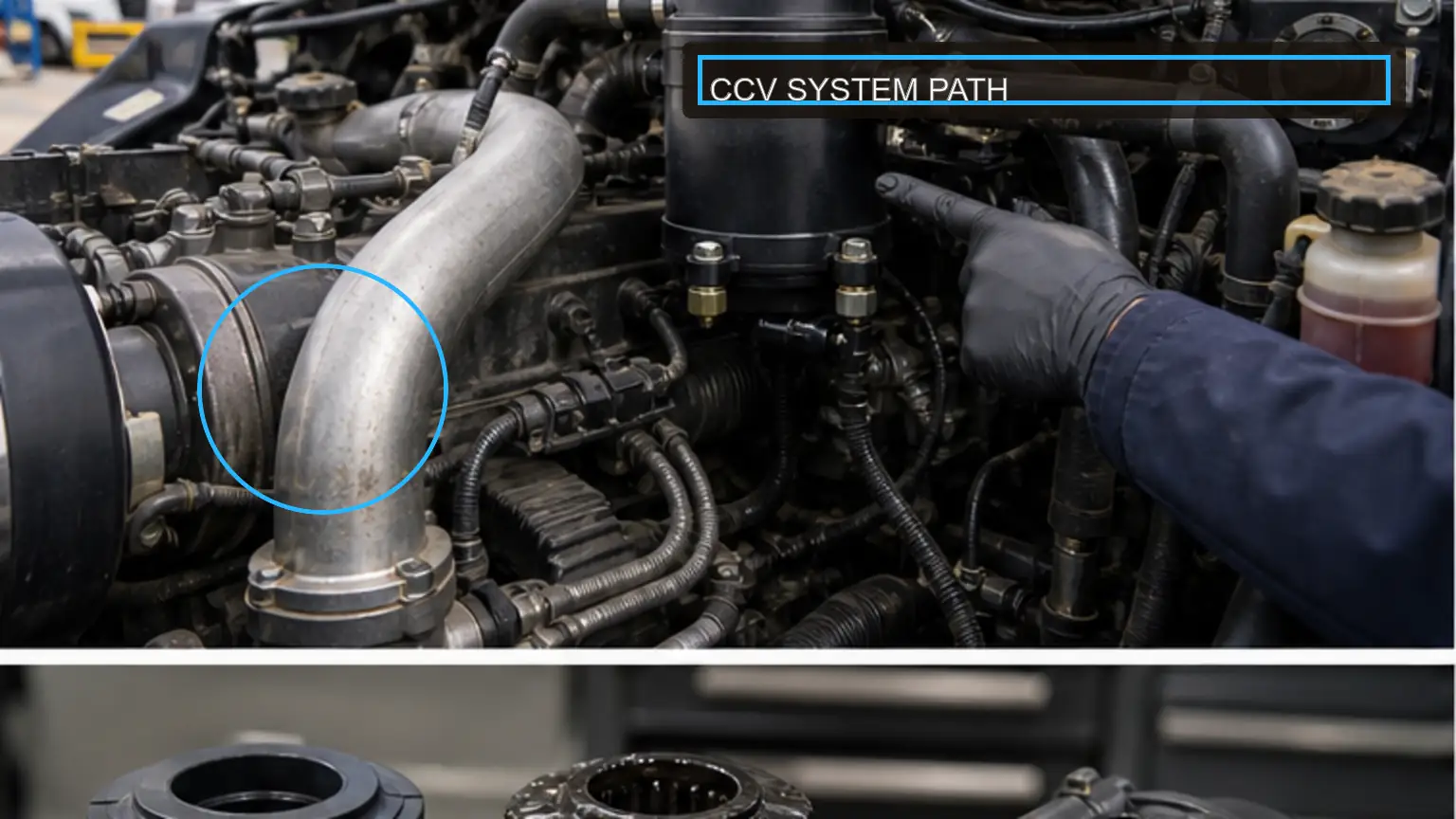
Record dirty blow-by inlet, coalescing element, pressure-control or bypass valve, oil drain, clean-gas outlet, and intake return as one evidence set. Before changing any hose, seal, element, valve, or electrical connection, the fleet technician should identify the vehicle, engine, component reference, date, operating state, and instrument.
Use the engine or system maker's procedure when one is available, and record any approved deviation before testing.
Dirty blow-by inlet: record the condition or result for dirty blow-by inlet; tie the dirty blow-by inlet entry to the vehicle, engine, date, and operating condition.
Coalescing element: for coalescing element, document the applicable specification or observation; tie the coalescing element entry to its method and reviewer.
Pressure-control or bypass valve: explain why pressure-control or bypass valve matters; cite the source or measured limit used for pressure-control or bypass valve.
Oil drain: use oil drain to test the suspected cause; when the oil drain evidence conflicts, define the next check.
Clean-gas outlet: retain a photograph, reading, or source note for clean-gas outlet; use the clean-gas outlet evidence to reproduce the decision.
Intake return: record the condition or result for intake return; tie the intake return entry to the vehicle, engine, date, and operating condition.
A missing hose, reversed port, stuck valve, or blocked oil return can imitate a failed element. Resolve a conflict by returning to the mapped interfaces and preserving the original physical and measured evidence. Accessibility is not proof of cause.
Close the map only after the inlet, treatment stage, controls, outlet, and any return path form one documented route. Name the missing connection whenever the path remains uncertain.
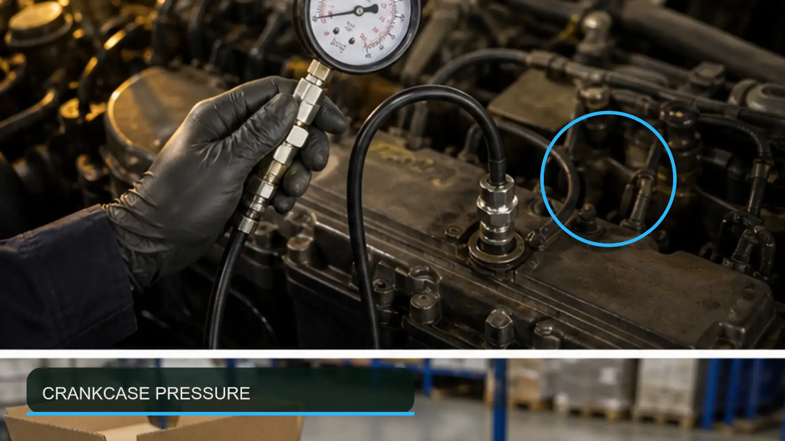
Evaluate approved test point, calibrated manometer, warm engine, idle and loaded readings, ambient correction, and repeatability together rather than as isolated observations. The diesel-system specialist should preserve the as-found condition and tie every result to the exact vehicle, engine, operating state, and test equipment.
Keep the units and test condition beside each result; a value without speed, load, temperature, or method cannot support a replacement decision.
Approved test point: record the condition or result for approved test point; tie the approved test point entry to the vehicle, engine, date, and operating condition.
Calibrated manometer: for calibrated manometer, document the applicable specification or observation; tie the calibrated manometer entry to its method and reviewer.
Warm engine: explain why warm engine matters; cite the source or measured limit used for warm engine.
Idle and loaded readings: use idle and loaded readings to test the suspected cause; when the idle and loaded readings evidence conflicts, define the next check.
Ambient correction: retain a photograph, reading, or source note for ambient correction; use the ambient correction evidence to reproduce the decision.
Repeatability: record the condition or result for repeatability; tie the repeatability entry to the vehicle, engine, date, and operating condition.
Pressure data must be tied to engine speed, load, temperature, and the engine maker's limit. If two readings disagree, repeat them at the same speed, load, temperature, and test point before replacing the element or opening a warranty claim.
Approve the measured step when the test point, instrument, stabilization state, demand, units, and repeated value can be reproduced by a second technician.
Crankcase ventilation filter system layout with the principal test points identified on a heavy-duty diesel application.
The working record should connect pressure before and after element service, cylinder condition, leak-down or maker-approved blow-by test, oil consumption, and smoke pattern. The receiving inspector should note when and where each check was made so that a later reviewer can reproduce the reasoning.
Compare repeated readings under the same conditions before treating a change as evidence of improvement.
Pressure before and after element service: record the condition or result for pressure before and after element service; tie the pressure before and after element service entry to the vehicle, engine, date, and operating condition.
Cylinder condition: for cylinder condition, document the applicable specification or observation; tie the cylinder condition entry to its method and reviewer.
Leak-down or maker-approved blow-by test: explain why leak-down or maker-approved blow-by test matters; cite the source or measured limit used for leak-down or maker-approved blow-by test.
Oil consumption: use oil consumption to test the suspected cause; when the oil consumption evidence conflicts, define the next check.
Smoke pattern: retain a photograph, reading, or source note for smoke pattern; use the smoke pattern evidence to reproduce the decision.
A new filter cannot correct ring, liner, or piston damage that produces abnormal gas volume. When component restriction and upstream-condition evidence point in different directions, keep the conclusions separate until both sides are measured.
Release the cause decision when component service evidence and an upstream-condition test explain the complaint without forcing either result to fit the preferred theory.
A reliable fault path links turbo inlet film, compressor outlet, charge-air hose, intercooler low point, oil feed and drain, and crankcase pressure. Before disturbing the system, the technical buyer should photograph the interfaces and record the engine identity, operating condition, instrument, and units.
If the maker specifies a dedicated test point, tool, sequence, or limit, that requirement controls the check.
Turbo inlet film: record the condition or result for turbo inlet film; tie the turbo inlet film entry to the vehicle, engine, date, and operating condition.
Compressor outlet: for compressor outlet, document the applicable specification or observation; tie the compressor outlet entry to its method and reviewer.
Charge-air hose: explain why charge-air hose matters; cite the source or measured limit used for charge-air hose.
Intercooler low point: use intercooler low point to test the suspected cause; when the intercooler low point evidence conflicts, define the next check.
Oil feed and drain: retain a photograph, reading, or source note for oil feed and drain; use the oil feed and drain evidence to reproduce the decision.
Crankcase pressure: record the condition or result for crankcase pressure; tie the crankcase pressure entry to the vehicle, engine, date, and operating condition.
Oil near a compressor housing is location evidence, not proof of a turbo seal failure. A downstream symptom must be reconciled with upstream supply, control, and return conditions before a convenient component is blamed for the system fault.
Complete the symptom trace when upstream observations, component behavior, downstream evidence, and the control state agree on the probable source.
Technician performing a controlled crankcase ventilation filter measurement with calibrated workshop instruments.
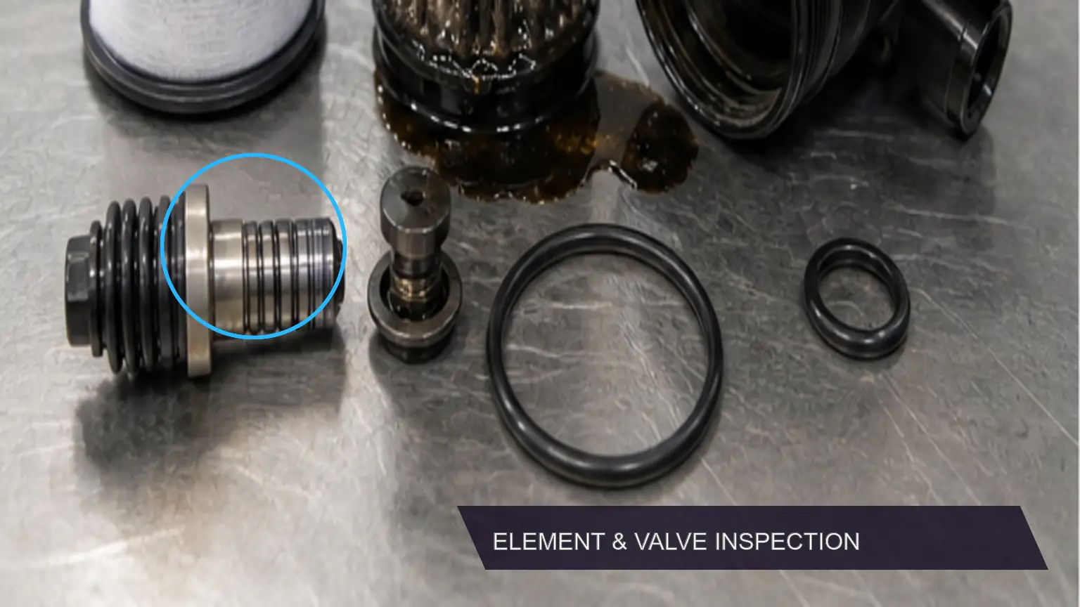
Review media saturation, collapse, seal position, bypass movement, pressure regulator, drain restriction, ice, sludge, and heat damage within the same diagnostic sequence. The warranty analyst should keep the original condition intact until the decisive measurements and photographs have been captured.
Photographs should show the component identity and the measured location, not merely the general engine compartment.
Media saturation: record the condition or result for media saturation; tie the media saturation entry to the vehicle, engine, date, and operating condition.
Collapse: for collapse, document the applicable specification or observation; tie the collapse entry to its method and reviewer.
Seal position: explain why seal position matters; cite the source or measured limit used for seal position.
Bypass movement: use bypass movement to test the suspected cause; when the bypass movement evidence conflicts, define the next check.
Pressure regulator: retain a photograph, reading, or source note for pressure regulator; use the pressure regulator evidence to reproduce the decision.
Drain restriction: record the condition or result for drain restriction; tie the drain restriction entry to the vehicle, engine, date, and operating condition.
Ice: for ice, document the applicable specification or observation; tie the ice entry to its method and reviewer.
Sludge: explain why sludge matters; cite the source or measured limit used for sludge.
Heat damage: use heat damage to test the suspected cause; when the heat damage evidence conflicts, define the next check.
Preserve the removed condition before cleaning so warranty evidence is not erased. Photograph any altered seal, valve, drain, or media condition before cleaning because the removed evidence may decide whether the case is service-related or product-related.
Finish this inspection after every named component, interface, control, damage pattern, and measurement is tied to the application record.
Normal and failed crankcase ventilation filter conditions compared during incoming or warranty inspection.
The replacement decision depends on consistent evidence for engine serial, housing reference, element dimensions, flow direction, valve configuration, service interval, and temperature range. The supplier-quality engineer should document the application, component identity, method, units, temperature, and repeat result.
State what each observation proves, what it rules out, and which alternative cause remains open.
Engine serial: record the condition or result for engine serial; tie the engine serial entry to the vehicle, engine, date, and operating condition.
Housing reference: for housing reference, document the applicable specification or observation; tie the housing reference entry to its method and reviewer.
Element dimensions: explain why element dimensions matters; cite the source or measured limit used for element dimensions.
Flow direction: use flow direction to test the suspected cause; when the flow direction evidence conflicts, define the next check.
Valve configuration: retain a photograph, reading, or source note for valve configuration; use the valve configuration evidence to reproduce the decision.
Service interval: record the condition or result for service interval; tie the service interval entry to the vehicle, engine, date, and operating condition.
Temperature range: for temperature range, document the applicable specification or observation; tie the temperature range entry to its method and reviewer.
A visually similar element may change restriction or oil-separation performance. Do not approve a look-alike replacement until its flow direction, valve arrangement, interfaces, and operating range match the engine record.
Accept the replacement match only when the engine reference, dimensions, interfaces, flow direction, valve function, and temperature range agree with approved evidence.
Release planning should bring together baseline pressure, service trigger, lot traceability, seal and valve checks, protected packaging, and post-install verification. The workshop supervisor should connect the technical findings to the approved sample, incoming lot, installation record, and follow-up check.
The final record should allow purchasing, service, and warranty teams to reach the same conclusion without relying on memory.
Baseline pressure: record the condition or result for baseline pressure; tie the baseline pressure entry to the vehicle, engine, date, and operating condition.
Service trigger: for service trigger, document the applicable specification or observation; tie the service trigger entry to its method and reviewer.
Lot traceability: explain why lot traceability matters; cite the source or measured limit used for lot traceability.
Seal and valve checks: use seal and valve checks to test the suspected cause; when the seal and valve checks evidence conflicts, define the next check.
Protected packaging: retain a photograph, reading, or source note for protected packaging; use the protected packaging evidence to reproduce the decision.
Post-install verification: record the condition or result for post-install verification; tie the post-install verification entry to the vehicle, engine, date, and operating condition.
Release a replacement lot only when identity and functional evidence agree. A lot can move to released inventory only after the sample result, packaging identity, installation check, and responsible reviewer are linked in one record.
Release the fleet standard after purchasing, receiving, service, and warranty teams can follow the same baseline, trigger, lot, installation, and follow-up record.
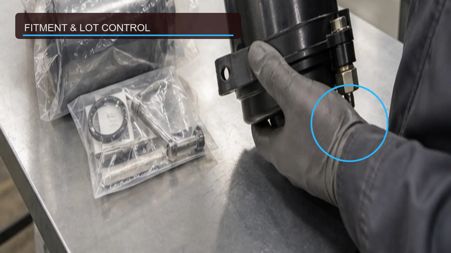
Crankcase ventilation filter fitment, clean packaging, and traceable batch-release checks for a heavy-duty order.
A useful crankcase ventilation filter RFQ begins with the exact engine family, serial or arrangement evidence, original reference, physical interfaces, system position, measured fault symptom, test conditions, monthly quantity, destination, and expected duty. It also states whether the offer is a new aftermarket replacement or another explicitly declared condition allowed for the assembly. Unverified genuine or OE language should not be inferred from appearance, packaging color, or a seller's keyword.
Include an approved crankcase ventilation filter sample process that covers CCV system mapping, filter restriction, crankcase pressure, blow-by separation, oil return, turbo oil carryover, fitment, and lot acceptance. Compare the sample with the turbo oil-drain and crankcase-pressure diagnosis guide, but keep public product pages as research aids rather than application authority. The supplier should return a drawing or structured data sheet, photographs of the actual configuration, functional evidence relevant to this failure, and the packaging proposal before production release.
Legal seller and manufacturing or remanufacturing source
Exact part and application references with declared cross-reference basis
Included sensors, valves, seals, fittings, caps, and service hardware
Sample quantity, functional test method, acceptance limit, and report format
MOQ, lead time, Incoterm, warranty route, claim turnaround, and core terms where applicable
Lot code, date code, carton label, moisture and shock protection, and change notification
Receiving inspection should identify the crankcase ventilation filter shipment before opening every protective cap. Compare the label, housing reference, connector and port layout, mounting geometry, sealing surfaces, included hardware, and lot code with the approved application and released sample record. Sample checks should use the method and units agreed during approval; improvised pass limits create disputes rather than quality control.
After the crankcase ventilation filter is installed, follow the maker's hose routing, seal installation, torque, oil-drain protection, and leak-check procedure and all applicable safety instructions. Recreate the operating condition that produced the original complaint as closely as practical, watch for leaks and abnormal pressure or temperature, and retain the first-run and loaded results. A stable idle without a loaded pressure check does not prove that the repair will survive normal duty.
No. The location and severity are useful evidence, but surrounding pressure, flow, valves, hoses, drains, and engine condition can create a similar appearance. Measure the complete ventilation and oil path before assigning the cause.
The number is a strong crankcase ventilation filter identity field, not the entire approval. Verify the engine application, interfaces, included accessories, product condition, functional data, packaging, warranty owner, and lot traceability required by this guide.
Quarantine an affected crankcase ventilation filter lot when identity, geometry, functional sample results, packaging, or declared source differs from the approved record. Do not mix the disputed units with released inventory while the supplier reviews the documented deviation.
A sound CCV decision separates filter restriction from engine blow-by and turbo-related oil evidence. Preserve the oil pattern, compare crankcase pressure with engine condition, and confirm valve, element, drain, and compressor-path findings before assigning the cause.
For a traceable decision, review the heavy-duty turbocharger catalogue, use the heavy-duty turbocharger sourcing guide, and send the operating data through the B2B contact page. The RFQ should describe the measured engine and ventilation path, not only the filter keyword.