ELECDURA NETWORK

Your Whole New Supply Chain For Heavy-Duty Parts
Whatsapp:
+86 18915027366
Phone:
+86 18915027366
Views: 0 Author: Site Editor Publish Time: 2026-08-07 Origin: Site
A wastegate actuator can move during a bench test and still be wrong for the turbocharger being supplied. Movement confirms a response under the conditions applied. It does not, by itself, confirm the specified opening point, rod travel, leak-tightness, linkage setting or boost regulation on the engine.
For a heavy-duty parts importer or distributor, that distinction matters whenever a supplier presents a photograph, a short test video or a pressure reading as proof that a replacement turbocharger is ready for a particular application. The useful question is not simply “Did the rod move?” It is “Which assembly was tested, under which specification, and which purchasing decision does the record actually support?”
This guide focuses on pneumatically controlled wastegate systems after their identity and approved test method have been established. It explains how a qualified technician's test can be interpreted by a purchasing or quality team. It is not a universal pressure-setting procedure: pressure-operated, vacuum-operated, electronic and variable-geometry controls must not be treated as interchangeable test systems.
A wastegate changes the exhaust-gas flow through a turbocharger turbine by opening a bypass path. Depending on the design, its actuator may respond to a pressure signal or another approved form of control. Some arrangements route the source through a boost-control valve rather than directly to the actuator.
A separate category of turbochargers uses variable turbine geometry, whose vanes and actuator may require electronic commands, position feedback and application-specific calibration. Visible rods, housings or connectors are not sufficient to determine the correct test method.
Before any pressure or vacuum is applied, confirm the complete turbocharger reference, actuator identity and applicable engine configuration from reliable documentation. If the control type or service procedure cannot be confirmed, do not improvise a bench test.
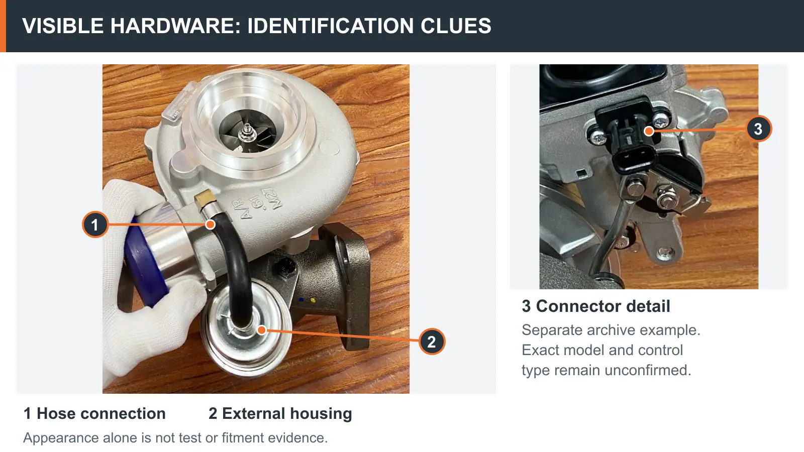
Figure 1. Real archive photographs with visible hardware identified. The connector detail comes from a separate assembly. Exact models and control types remain unconfirmed; appearance does not establish test results or fitment.
Identified system | What the testing route depends on | What not to assume |
|---|---|---|
Pressure-operated pneumatic wastegate | Approved pressure source, connection point, model-specific pressure/travel criteria and linkage arrangement | That shop air, a generic opening pressure or a visually similar actuator is acceptable |
Vacuum-operated pneumatic wastegate | Approved vacuum source, correct port routing and model-specific movement and holding criteria | That a pressure test is equivalent, or that every pneumatic actuator tolerates vacuum |
Electronic actuator or electronically controlled VGT/VNT | Appropriate scan-tool or manufacturer diagnostic procedure and relevant mechanical/calibration checks | That moving a rod by hand or applying a pneumatic signal will verify the actuator |
Garrett cautions that vacuum can damage certain OEM-style pressure-operated actuators. Conversely, products specifically designed for vacuum operation exist. The correct instruction comes from the identified unit's service information—not its appearance or an online test value copied from another model.
A professional test is valuable when its conditions can be reconstructed and its results compared with an applicable requirement. A buying team does not need to perform every measurement, but it should be able to determine whether the report belongs to the goods being offered.
Record the complete turbocharger and actuator identifiers, the host engine or application when relevant, and whether the tested item is a separate actuator or an actuator mounted on the turbocharger assembly. Record the supplier's document revision or the manufacturer procedure being used.
An OE-style reference, an aftermarket cross-reference and a supplier's internal number can be useful search fields. They are not automatically proof of mechanical or control-system interchangeability. If two references are being treated as equivalents, request the basis for that match.
An appropriately trained technician should follow the applicable service procedure, with the hardware secured and at the specified condition, using a suitable regulated source and measurement instruments. The test record should identify the connection point, pressure or vacuum input, instrument units and required measuring position.
Do not connect unrestricted compressed air or choose a test limit from an unrelated model. An actuator's safe input range and its specified movement points are application-dependent. If those limits are unavailable, the appropriate result is TEST METHOD NOT CONFIRMED, not a guessed setting.
The beginning of rod movement is one possible observation. It is not necessarily the manufacturer's specified acceptance point. A procedure may define displacement at a particular signal, travel over a range, return position, or other conditions. The report should identify each specified point and its acceptance criterion.
For example, the statement “rod moves when pressure is applied” establishes only that movement was observed. Without a reference procedure, input value, defined travel point and result, it cannot establish that the actuator is correctly set for the ordered assembly.
Where the approved test includes a pressure or vacuum holding check, record the prescribed starting condition, observation interval and result. A drop observed in a connected test rig can involve a hose, fitting, instrument or other connection—not only the actuator diaphragm. These possible sources must be distinguished using the applicable method.
A recorded hold result also does not prove the wastegate lever moves freely or the flap seats correctly. Pneumatic integrity and mechanical operation are related, but they are not identical tests.
If required by the procedure, the technician records return movement, repeat observations, linkage condition and evidence of binding or interference. The rod, lever, retaining hardware and wastegate mechanism should be reviewed within the permitted service scope.
Rod adjustment or preload should not be changed merely to make a reading look closer to a target. An incorrect adjustment can change wastegate operation, and the correct setting is specific to the assembly and service instructions. Record the as-received setting before any authorized intervention.
A useful report separates the observed fact, the limited conclusion and the unresolved decision. Without this separation, a favorable-looking result can be mistakenly promoted into evidence of full turbocharger suitability.
Observation in the report | What it can support | What it cannot establish on its own | Appropriate next check |
|---|---|---|---|
Rod movement observed at a documented input | The identified unit responded under that condition | Correct opening point, full travel, leak performance or matching to the quoted assembly | Compare all required points with the applicable procedure |
Rod travel recorded at specified test points | Movement data for the tested configuration | Correct linkage setting if the installation or method differs; installed boost regulation | Confirm mounting configuration, linkage condition and criteria |
Pressure/vacuum holding result recorded | Holding behavior of the tested setup under defined conditions | That any leakage is necessarily inside the actuator; that mechanical linkage is sound | Check test connections and apply the specified leakage assessment |
No movement during an attempted test | A failure to respond under the conditions attempted | That the actuator alone is defective when the input type, route or fixture is uncertain | Verify unit identity, source, connections and mechanical freedom |
Supplier video shows a moving rod, without identifiers or readings | Visible motion in the filmed example | The condition of the buyer's ordered reference or batch | Request an identifiable test record tied to the quoted goods |
Bench checks meet the stated criteria | The tested unit met those specific bench requirements | Entire vehicle boost performance, long-term durability or all application compatibility | Verify system-level conditions and order configuration |
The crucial distinction is recorded observation versus acceptance against an identified specification. A test can be properly performed yet answer a narrower question than the purchasing team assumes.
If a wastegate actuator fails to respond as expected, several connected components may require investigation. These include the signal line and fittings, diaphragm or actuator canister, linkage, wastegate lever and the bypass valve mechanism. The manufacturer-approved troubleshooting route determines which item can be serviced and how its condition is established.
The Cummins/Holset troubleshooting matrix distinguishes a failed diaphragm, seized valve, leaking hose and incorrectly set wastegate mechanism. Those are different failure paths, not interchangeable diagnoses. It also warns that common turbocharger complaints can arise from other engine or air-path faults.
For a supplier-claim review, ask whether the reported defect has been located, not merely described. Consider the difference between these statements:
“The control circuit did not hold the specified test condition.” This describes a result for the connected circuit. It does not identify the failing component until the method isolates it.
“The actuator diaphragm was confirmed faulty using the applicable procedure.” This is a narrower component conclusion and should be supported by corresponding test evidence.
“The wastegate lever binds in the tested mechanical condition.” This concerns the mechanism and may not be corrected by installing another pneumatic canister.
For a replacement quotation, the distinction changes the possible supply scope. Depending on the identified product and approved service route, the remedy may involve a hose or control component, an authorized actuator service, a turbine-housing-related repair or a complete turbocharger assembly. Replacing a CHRA alone does not verify or repair the external wastegate control arrangement.
A pneumatic bench setup evaluates defined actuator or mechanical behavior away from the full engine control environment. On the vehicle, boost is influenced by the pressure source, control valve if fitted, hose routing, mechanical linkage, engine operating conditions and the wider intake and exhaust systems.
An engine with low boost does not automatically need a wastegate actuator. An engine with overboost does not automatically have a stuck wastegate. Charge-air leakage, intake or exhaust restrictions, sensor issues and other faults can produce overlapping symptoms. The correct diagnostic route depends on the engine and turbocharger configuration.
In a controlled workshop investigation, relevant available data may include the actual measured boost, the control command where present, operating speed/load and checks of the charge-air and exhaust paths. What is measured and how it is interpreted must follow the application-specific service information. A bench actuator signal is not a universal target for manifold boost, and different measurements should not be compared simply because both use pressure units.
For technical purchasing teams, this leads to a practical decision rule:
Approve a component test only for the requirement it was designed to verify; do not use it as a substitute for application fitment or a complete engine diagnosis.
Before treating a test sheet as acceptance evidence, compare it with the quotation, product markings and the actual supply scope. A perfect result from another actuator or a different assembly reference does not establish conformity for the item being purchased.
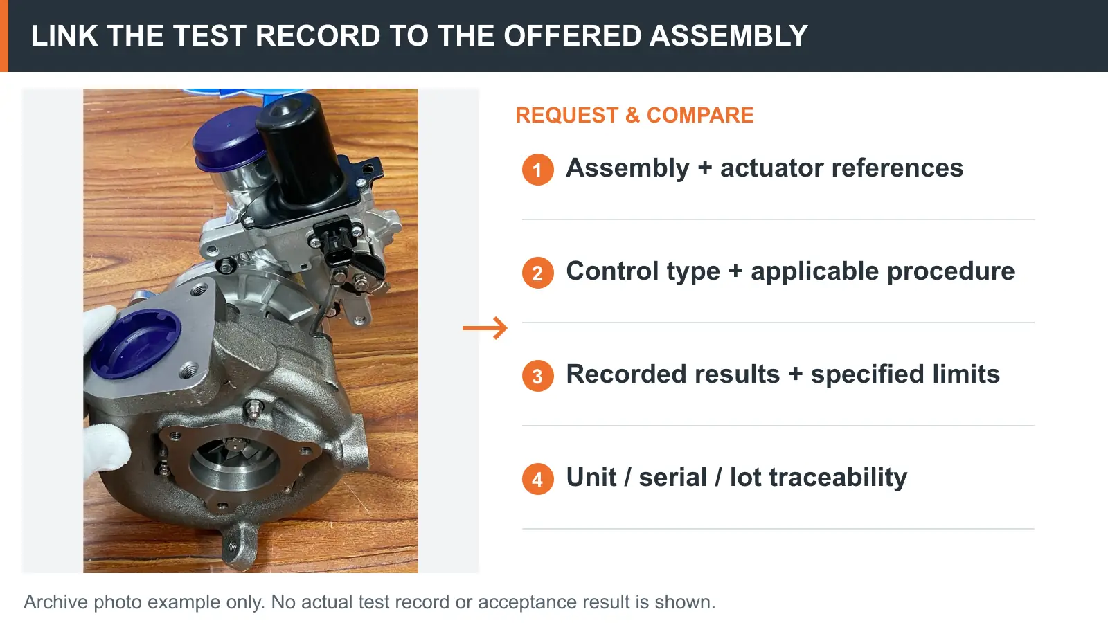
Figure 2. Compare any claimed test evidence with the actual offered assembly and applicable specification. This archive photo is an identification example; no actual test record, readings or acceptance result is shown.
Requested field | Why it matters to the purchasing decision | If missing or inconsistent |
|---|---|---|
Complete turbocharger reference and actuator identifier | Establishes the identity of what was tested | Put the claimed match on hold until identified |
Engine/application details where required | Confirms which control configuration and criteria apply | Ask for the exact application basis |
Control type and permitted input | Determines whether pressure, vacuum or a non-pneumatic test is appropriate | Do not accept the method as applicable |
Test procedure, issuing source and revision | Shows where the acceptance criteria came from | Request the applicable procedure or a defensible reference |
Tested object and mounting state | Distinguishes a standalone component from an installed assembly | Clarify what the report actually covers |
Connection point, equipment and units | Makes the observation interpretable and repeatable | Request a corrected or complete record |
Required input/travel or hold points | Links readings to defined checks rather than visual impressions | Do not substitute an arbitrary movement value |
Recorded results against specified limits | Shows whether the defined checks were passed or failed | Mark the conformity claim unresolved |
Unit, serial or lot identification where applicable | Connects the evidence to the actual offered goods | Ask how the sample or record relates to the shipment |
Remaining installation or control-system checks | Separates bench verification from on-engine approval | Retain the unresolved checks in the order file |
Not every purchase requires the same level of documentation. The necessary evidence depends on application risk, customer requirements, supplier declarations and the contractual inspection arrangement. What matters is that a claimed test result is not used for more than it proves.
Example A — Movement video only (hypothetical). A supplier provides a close-up video of a wastegate rod moving. No assembly reference, input measurement or test standard appears. The video may illustrate operation, but it does not validate the offered turbocharger. Decision: request identifiable specifications and corresponding records before technical acceptance.
Example B — Plausible report, wrong reference (hypothetical). A pressure/travel report names a different actuator from the one shown on the quotation. Even if the recorded results pass that report's criteria, the documentation is not yet traceable to the order. Decision: hold the equivalence claim pending a documented cross-reference and correct test applicability.
Example C — Valid bench result, ongoing low-boost complaint (hypothetical). The documented pneumatic checks meet the applicable specification, but the vehicle still reports low boost under load. The bench result reduces uncertainty about that tested behavior; it does not exclude a control valve, hose, air-path or engine-side problem. Decision: continue application-specific vehicle diagnosis rather than assuming a replacement turbocharger is required.
These examples are reasoning illustrations, not Elecdura customer cases or actual test outcomes.
The correct order depends on what has actually been identified as defective, what the manufacturer permits to be serviced and whether the replacement configuration is confirmed.
Continue diagnosis when the control architecture, failure location, test method or application remains uncertain. A large purchase order should not substitute for an unresolved technical match.
Request authorized component service details when the applicable service documentation supports an actuator, hose or mechanism-level remedy. Confirm the supplier's real supply scope and any setting or calibration responsibility; do not assume every actuator is separately available.
Evaluate a complete turbocharger replacement when the relevant failure, service policy or application requirement calls for the assembly. Verify the full turbocharger reference, actuator configuration, mechanical interfaces and any required matching or calibration evidence—not just the CHRA reference.
For repeated wholesale purchases, the technical record should be tied to a defined order reference and, where relevant, a sampled unit or lot. Changes in actuator model, housing, control interface or supplied configuration should trigger a fresh review rather than automatic acceptance under the previous part number.
A concise technical RFQ can prevent an unnecessary second round of quotations. Buyers can share:
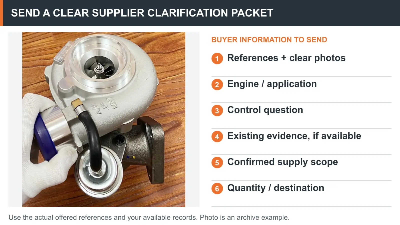
Identification: Complete turbocharger and actuator references, available original labels and clear photographs.
Application: Engine or vehicle/equipment details, market configuration and any known control-system information.
Technical question: Whether the intended part is pressure-, vacuum- or electronically controlled, and which exact comparison needs resolving.
Existing evidence: Applicable test reports, service-document references and notes on any observed failure or mismatch.
Supply scope: Whether a complete turbocharger, CHRA or another specifically confirmed component is being requested.
Commercial plan: Expected quantity by reference, destination and any agreed inspection or documentation requirement.
Figure 3. Build the clarification packet using your actual references, application details and available records. The photograph is an archive example, not a documented test specimen or confirmed quotation item.
A practical message to a supplier might read:
Please confirm whether the quoted turbocharger and actuator references match the attached application details. If you provide a wastegate test record, please identify the unit or lot tested, the applicable procedure, the input and travel/holding criteria, and the results. Please also clarify which assembly or components are included in the quotation and which checks remain the installer's responsibility.
This does not assume that every supplier has every report, or that the absence of a document automatically proves a defective part. It ensures that any technical claim used to approve a purchase has a clear basis.
A wastegate actuator pressure test can provide valuable evidence about a specific identified unit under defined conditions. It cannot independently prove correct fitment, full boost-control performance or the condition of every associated turbocharger component.
Before buying replacement stock, verify the actuator type, the applicable specification, the recorded test points and the link between the report and the goods being offered. Where important fields remain unresolved, request clarification or further diagnosis rather than turning an incomplete observation into a pass decision.
Elecdura supplies aftermarket heavy-duty turbocharger and CHRA products. For a bulk sourcing inquiry, send the complete reference numbers, application information and estimated quantities to info@elecdurauto.com. Elecdura can review the request against its confirmed supply scope; availability, matching and documentation requirements must be verified for the specific item.
The following sources provide general technical context. Their procedures and numerical specifications apply only within their stated product and application scope: