Your Whole New Supply Chain For Heavy-Duty Parts
Whatsapp:
+86 18915027366
Phone:
+86 18915027366
Views: 0 Author: Site Editor Publish Time: 2026-07-29 Origin: Site
An A/C compressor clutch that slips, chatters, engages only when cold, or refuses to pull in can stop cab cooling without proving that the compressor itself has failed. Air gap, coil force, system voltage, ground quality, relay control, belt condition, bearing drag, and refrigerant-pressure protection all affect engagement. Replacing the complete compressor before separating those factors can create repeat downtime.
Heavy-duty truck, agricultural, construction, and bus systems also use different voltages, pulley grooves, mounting patterns, coil connectors, and control strategies. Buyers reviewing the Elecdurauto heavy-duty A/C compressor range should therefore match the physical compressor and clutch while preserving the vehicle’s electrical and refrigerant requirements.
This guide presents an evidence-based sequence for inspecting air gap, measuring coil resistance and current, testing voltage drop, checking thermal behavior, evaluating pulley and hub condition, and deciding whether the clutch, coil, bearing, control circuit, or complete compressor belongs in the repair scope.
A disciplined test also improves stocking decisions because it identifies whether demand belongs to a complete compressor, a serviceable clutch, an electrical component, or a vehicle-side repair rather than treating every loss of cooling as the same product opportunity safely.
Start by recording whether the clutch never engages, engages intermittently, releases after warming, slips under load, chatters, or remains engaged when it should release. Note ambient temperature, cab demand, engine speed, blower setting, refrigerant pressures, fault codes, and the time required for the symptom to appear. An intermittent hot failure requires measurements during the event, not after the vehicle cools.
Verify whether the controller is actually requesting compressor operation. Low refrigerant pressure, high discharge pressure, evaporator freeze protection, engine overheat, wide-open throttle logic, network faults, or an HVAC module decision can intentionally remove the request. On variable-displacement or clutchless designs, the visible pulley behavior and control method may differ from a conventional electromagnetic clutch.
Save the wiring diagram and identify every stage between command and coil: fuse, relay, pressure sensors or switches, module output, connector, ground, and any thermal protection. This map prevents a missing command from being mistaken for weak magnetism and gives the parts buyer an exact electrical configuration.
The compressor, pulley, hub, connector, and mounting arrangement should be identified before electrical or gap measurements begin.
Engagement pattern, temperature, engine speed, and operating delay
Controller request, pressure protection, and relevant fault codes
System voltage, clutch design, connector, and ground path
Wiring diagram from command source to coil
Do not test clutch pull-in as a component fault until the system request and protective logic are understood. An intentional command removal is not a failed clutch.
With the engine isolated, inspect belt tension, alignment, contamination, glazing, cracks, and pulley groove condition. Check the clutch hub for heat discoloration, scoring, loose fasteners, broken rubber elements, missing shims, and uneven wear. Rotate the pulley according to the service procedure and listen for rough bearing noise or contact.
A dragging compressor, failed pulley bearing, or misaligned belt can overload a clutch that has adequate air gap and coil force. Metal dust around the hub, blue surfaces, or a burnt odor supports repeated slip, but the cause may be excessive compressor torque rather than an electrical fault. Do not install a new clutch onto a seized or contaminated compressor.
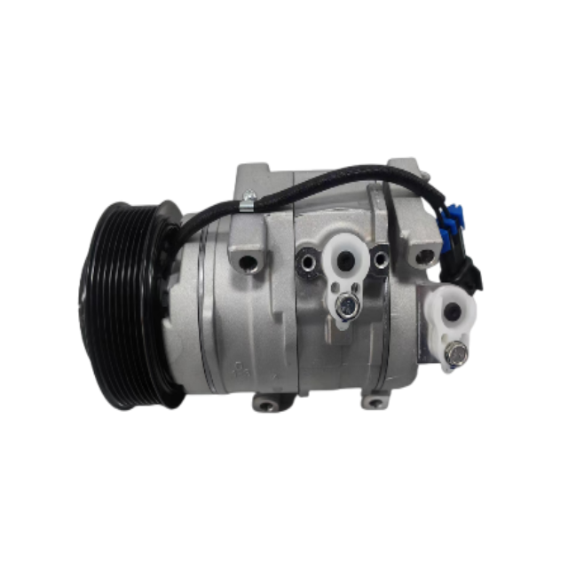
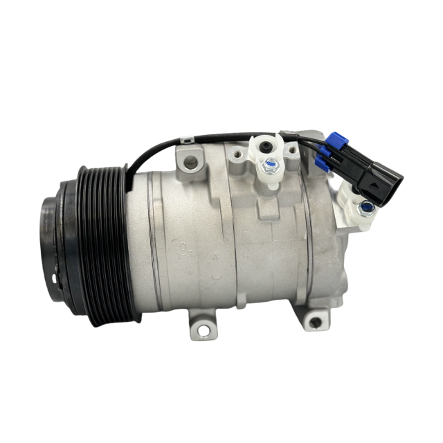
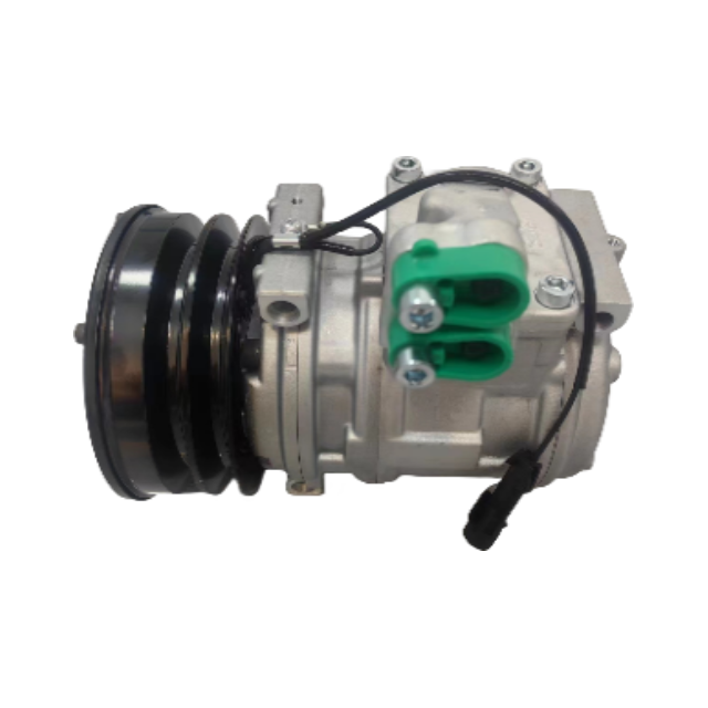
Photograph the label, mount, rear head, ports, pulley grooves, diameter, hub, coil connector, and belt path. These features are vital if a replacement such as the H10 John Deere A/C compressor is being considered. Model family alone does not confirm voltage, groove count, port orientation, or bracket fit.
Belt tension, alignment, groove condition, and contamination
Pulley bearing noise, play, temperature, and drag
Hub wear, heat marks, shims, fastener, and friction faces
Compressor shaft torque and evidence of internal seizure
Repair belt, bearing, alignment, or compressor drag before judging coil force. A clutch cannot survive when the driven assembly or belt system exceeds its designed load.
Use the specified feeler-gauge method at several evenly spaced points around the hub. Do not force the gauge or measure across raised damage. Record each position because an acceptable average can hide a tapered gap caused by hub distortion, debris, worn splines, uneven shims, or a bent plate. Compare the exact clutch family with verified service limits.
An excessive gap reduces magnetic force at the friction surfaces and commonly causes hot non-engagement because coil resistance rises as temperature increases. A gap that is too small can create drag, heat, noise, and premature wear. If the values vary greatly around the circumference, simply removing a shim may not restore parallel engagement.
Document instrument, locations, cold temperature, measured range, and published limit source. If no trusted specification is available, do not substitute a generic number from another compressor. The RFQ should ask the supplier to confirm the clutch air-gap specification and adjustment method for the proposed unit.
At least three circumferential measurement positions
Cold component temperature and gauge method
Minimum, maximum, spread, and exact published limit
Shim arrangement, hub runout, debris, and face condition
Adjust only when the clutch design and limit are verified and the friction faces remain serviceable. Uneven gap or mechanical damage requires deeper repair than shim removal.
Disconnect the coil as directed and measure resistance with a meter that has been checked for lead resistance and contact quality. Temperature matters: copper resistance rises when hot, so compare the reading with a specification at a known temperature or apply the manufacturer’s correction method. A cold reading inside a broad range may not reveal a heat-open winding.
Inspect the connector for spread terminals, corrosion, oil, seal damage, melted plastic, and weak retention. Flex the harness carefully while monitoring when an intermittent open is suspected. Test coil insulation to ground only with equipment and voltage approved for the circuit; an inappropriate insulation test can damage electronics or the winding.
The BH50101 Komatsu A/C compressor illustrates why product identification matters: coil voltage, pulley configuration, and connector details must agree with the application. A nominal 12-volt coil in a 24-volt fleet, or the reverse, creates immediate failure or unreliable pull-in.
Coil voltage, connector, pulley, and mounting details must match the heavy-duty application.
Meter lead compensation and clean terminal contact
Coil temperature and applicable resistance specification
Connector retention, seal, corrosion, and harness flex behavior
Approved coil-to-ground insulation method where specified
A stable cold resistance is not enough when the complaint is thermal. Repeat the measurement at the failure temperature or monitor the circuit until the winding opens or deviates.
Resistance predicts current only if actual coil voltage is known. Use an appropriate current clamp or in-series method and measure voltage at the clutch connector while the controller commands engagement. Compare initial and steady current with the circuit specification. Low current can result from excessive resistance in wiring or the winding; high current may indicate shorted turns or the wrong coil.
Observe how quickly the hub pulls in and whether it remains fully seated. Chatter may come from weak voltage, excessive air gap, a distorted face, relay bounce, controller cycling, or pressure protection. Do not repeatedly force engagement when the clutch slips; each event adds heat and can damage the hub, pulley bearing, and compressor nose.
Where an approved fused test lead is allowed, direct coil activation can separate the clutch from upstream control, but it must not bypass system safety in a way that runs the compressor under unsafe pressure or lubrication conditions. A pull-in test with the belt removed or system disabled may be preferable when service information permits.
Connector voltage and coil current during command
Initial pull-in speed and steady holding behavior
Chatter frequency, controller request, and relay state
Safe fused isolation method permitted by service information
Condemn the coil only when adequate voltage reaches it and current, pull-in, or hot holding behavior remains outside the verified requirement.
A meter showing battery voltage at an unloaded connector can hide a poor relay, fuse contact, splice, or ground. Measure from battery positive to the coil supply during engagement and from coil ground to battery negative at the same time. Segment any excessive loss across relay contacts, fuses, connectors, harness sections, module drivers, and ground points.
On electronically driven circuits, confirm whether the module switches the positive or ground side and whether pulse-width modulation is used. A conventional meter may display an average that needs oscilloscope or scan-data context. Never apply external power to a module-controlled wire until the circuit architecture is verified.
Heat-test suspicious connections because damaged crimps and relay contacts may rise in resistance after current flows. A thermal hot spot supports the electrical reading but does not replace it. Repair the circuit, repeat the air-gap and pull-in test, and confirm that the controller maintains the command.
Battery-positive to coil-supply voltage drop
Coil-ground to battery-negative voltage drop
Relay, fuse, splice, connector, driver, and ground segmentation
PWM or module-controlled waveform and command context
Do not replace the clutch or compressor for weak engagement until loaded voltage drop is inside the application limit at the actual failure temperature.
If the clutch works cold, monitor coil resistance or current, connector voltage, air gap, hub temperature, pulley temperature, discharge pressure, and controller request as the system warms. Use non-contact temperature tools with appropriate emissivity awareness or attached sensors placed safely away from rotating parts. Stop the test if slip or overheating appears.
A widening effective gap, reduced magnetic force, heat-open winding, relay failure, connector resistance, excessive high-side pressure, or compressor torque can all produce a hot release. Identify which value changes first. If the controller removes the request before the clutch releases, investigate system protection; if the command remains but current disappears, the electrical path or coil becomes more likely.
Map the recovery period. A coil that reconnects after cooling presents different evidence from a controller that resets after pressure falls. The final report should include time, temperatures, pressures, current, voltage, and command state at engagement, failure, and recovery.
undefined
Coil, hub, pulley, ambient, and compressor temperatures
Voltage, current, air gap, and command state
Suction and discharge pressure plus condenser airflow
Failure time, first changing value, and recovery time
Base the repair on the first parameter that leaves its normal condition, not on whichever component feels hottest after the clutch has already slipped.
A serviceable compressor with a verified replaceable clutch may need only a hub, coil, pulley bearing, or complete clutch set. The repair requires approved tools, correct puller and installer use, shaft protection, shim selection, retaining hardware, air-gap setting, and final runout inspection. Not every compressor supports clutch service in the vehicle.
Complete replacement is more appropriate when the compressor is seized, noisy internally, contaminated, leaking at non-serviceable areas, has damaged nose or shaft splines, or when a correct clutch assembly cannot be sourced and validated. If internal failure released debris, the system may require flushing or component replacement according to refrigerant-system guidance.
A product such as the BH51122 10PA17C A/C compressor should be matched by compressor model, voltage, mount, pulley, ports, rear head, oil and refrigerant requirements, and application. Buyers should define whether the order includes clutch, coil, oil quantity, seals, and protective caps.
Compressor torque, noise, leakage, contamination, and shaft condition
Clutch serviceability, tool access, shims, hub, coil, and bearing availability
System debris, flushing requirements, receiver-drier, and expansion control
Complete-unit fitment, oil, refrigerant, ports, mount, pulley, and voltage
Choose clutch-only repair only when the compressor and refrigerant circuit are healthy and the service procedure can restore verified air gap, retention, and alignment.
After evacuation, charging, or component service, follow the specified refrigerant and oil procedure. Confirm condenser airflow, fan operation, belt condition, suction and discharge pressures, vent temperature, evaporator control, and clutch cycling at a defined ambient condition and engine speed. A clutch that engages does not prove that the system cools correctly.
Repeat voltage, current, and temperature checks after the unit reaches a representative work cycle. Watch for slip dust, odor, chatter, rising air gap, abnormal bearing heat, or controller intervention. For machines that operate at low vehicle speed, verify condenser performance in the real airflow environment rather than relying only on a cool workshop bay.
Record the final refrigerant mass, oil action, pressure readings, vent performance, command state, coil current, hot air gap where specified, and inspection result. This becomes the baseline for future maintenance and supports supplier or installer warranty review.
Specified refrigerant charge and oil procedure
Pressures, vent temperature, ambient, airflow, and engine speed
Hot coil current, connector voltage, engagement, and cycling
Post-run hub, pulley, belt, bearing, and leak inspection
Release the vehicle or machine only after the clutch remains stable through the intended heat and load cycle and the refrigeration system delivers controlled cooling without abnormal pressure or slip.
A heavy-duty A/C compressor inquiry should include vehicle or equipment, engine, voltage, compressor model, OE references, mount photographs, pulley diameter and groove count, connector, port type and orientation, rear-head details, clutch air gap, coil readings, and the diagnosed repair scope. State quantity, destination, packaging, and whether a sample is required.
Use accurate positioning: an OE number can be used for matching, but an unverified replacement should be described as an aftermarket equivalent or OE-reference replacement, not as a genuine branded compressor. Ask the supplier to confirm compressor family, clutch voltage, pulley, mounting, oil, refrigerant, and application in writing.
Send the evidence through the Elecdurauto heavy-duty A/C inquiry page so technical review can precede a quotation. For repeat orders, retain the accepted label, dimensions, connector, clutch current, gap, packaging, and commissioning result as the batch reference.
Equipment, engine, voltage, model, OE reference, and quantity
Mount, pulley, connector, ports, rear head, oil, and refrigerant
Gap, resistance, current, voltage drop, pressure, and failure temperature
Sample approval, test evidence, packaging, lead time, and warranty process
Do not approve bulk supply until a sample matches the complete mechanical, electrical, and refrigerant interface and passes hot loaded commissioning.
A/C compressor clutch diagnosis becomes reliable when air gap, coil resistance, current, loaded voltage, control request, temperature, belt condition, compressor torque, and refrigerant protection are evaluated together. Excessive gap and a weak hot coil can look similar, while control or pressure logic may intentionally remove engagement.
For fleet and B2B buyers, the strongest replacement request includes the failure timeline, measurements, compressor identity, electrical configuration, pulley and mount, ports, refrigerant system, and acceptance test. That evidence prevents unnecessary complete-compressor replacement and makes any approved aftermarket unit easier to validate, stock, and support.