Your Whole New Supply Chain For Heavy-Duty Parts
Whatsapp:
+86 18915027366
Phone:
+86 18915027366
Views: 0 Author: Site Editor Publish Time: 2026-07-31 Origin: Site
A dual alternator system is not simply two charging units bolted to one engine. The architecture must define which loads each alternator serves, how voltage is sensed, whether output is paralleled, how current is shared, how batteries are isolated or combined, and what happens when one unit or cable path fails. Without that design, a second alternator can add heat, belt load, electrical noise, and diagnostic confusion without providing useful capacity.
Elecdurauto supplies heavy-duty alternator solutions for commercial trucks, buses, diesel engines, construction equipment, agricultural machinery, and high-load aftermarket applications. Products are positioned as OE-grade aftermarket replacements or equivalents for reference matching. A dual system must still be engineered around the vehicle and body-builder requirements.
This guide explains the main architectures, load calculations, control and protection decisions, failure-isolation methods, B2B sourcing requirements, and commissioning tests needed before a dual alternator installation is released.
Define the electrical objective before selecting hardware. Common goals include higher total capacity, better hot-idle output, separation of chassis and auxiliary loads, battery-bank isolation, or limited redundancy. Each goal leads to a different wiring, regulation, and fault-response design.
Both alternators feed the same electrical bus and battery system. The design must manage voltage-set-point tolerance, cable resistance, current sharing, sensing, protection, and circulating current. Identical model labels do not guarantee identical real-world regulation.
One alternator supports the chassis bank while the other supports body, hotel, refrigeration, communications, or work-equipment loads. Isolation devices, charge paths, grounds, and emergency cross-connect functions must be documented so a failure does not create an unintended backfeed.
Some severe-duty systems use one unit as primary and retain another for controlled redundancy. The changeover strategy must define monitoring, excitation, battery support, and how the standby unit is tested. An unexercised standby is not proven redundancy.
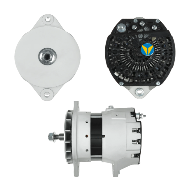
A high-output alternator is one component in a dual system that also depends on drive, controls, wiring, batteries, and protection.
List chassis, body, trailer, HVAC, refrigeration, liftgate, inverter, lighting, communication, pump, fan, heater, and battery-recovery loads. Record continuous amperage, peak amperage, duration, operating sequence, engine speed, ambient temperature, and which battery or bus receives the load.
A sum of every nameplate may oversize the system, while an average may miss a critical overlap. Build operating scenarios such as loading at idle, nighttime delivery, regeneration, emergency scene lighting, sleeper operation, or hydraulic work.
After engine start or deep auxiliary use, battery banks may absorb significant current. Set an acceptable recovery time and protect the batteries from an unsuitable charge rate. Charging demand belongs in the alternator capacity model even when no accessory changes.
Alternator output originates as mechanical power. Confirm bracket strength, belt wrap, groove count, tensioner capacity, pulley ratio, bearing load, crankshaft drive limits, vibration, and engine power at idle. A second alternator may require a dedicated drive or an approved accessory arrangement.
Electrical output divided by efficiency gives approximate mechanical input. Add both units at the expected operating point and include fan and belt losses. The engine control strategy may need to raise idle speed or limit loads to maintain stable operation.
Use crank and alternator pulley diameters to calculate shaft speed at idle and maximum engine speed. Confirm each unit stays inside its approved range. Inspect belt temperature, tensioner movement, dust, glazing, and alignment during loaded tests.
In a parallel system, small differences in set point or path resistance can make one alternator carry most of the load. Determine whether the regulators are approved for parallel operation, whether they communicate, and where each unit senses voltage. Do not assume two independent regulators will share evenly.
Differences in B+ and ground cable length, size, connections, or temperature change current distribution. Route and size the paths intentionally, use matched connection quality where sharing is required, and measure voltage drop at operating current.
If both regulators sense different points, they may respond to different voltage losses. If both sense one bus, the wiring and failure behavior must be approved. Document the sense location, protection, fallback mode, and acceptable voltage difference across all banks.
Protection must interrupt a cable fault without disabling unrelated safety systems or creating an uncontrolled battery connection. Size conductors, fuses or circuit protection, disconnects, busbars, lugs, insulation, and enclosures for continuous current, fault current, temperature, vibration, and service access.
Batteries and alternators can both energize a fault. Place protection according to the approved design and account for bidirectional current. A fuse only at one end of a long cable may leave the other source unprotected.
Map chassis, engine, alternator, battery, body, and auxiliary grounds. Parallel systems can develop unexpected return paths through small wires, communication shields, or mounting hardware. Measure voltage drop and current paths under the actual load.
Technicians need clear labels and a diagram for disconnects, combiners, and cross-connect devices. An emergency function should not depend on trial and error during a no-charge event.
Match voltage, output curve, regulator compatibility, mounting, pulley, rotation, cooling, environmental protection, terminals, communication, and application approval. In a parallel architecture, paired regulation behavior can matter more than individual maximum output.
A 40SI 12V 300A-320A J180 alternator illustrates a high-output single-unit path that may simplify wiring and control. A WB2443 24V PAD-mount alternator illustrates how voltage and mounting can differ even within a high-output direction. These examples help frame the decision; they are not automatic dual-system pairs.
Two air-cooled units add heat to the same compartment. In severe environments, a 55SI water-cooled alternator range can illustrate another thermal design direction, but cooling circuits, service capability, and application approval must be evaluated. Do not choose a cooling method from output alone.
Begin with the architecture diagram. Record battery state, bus voltages, engine speed, commanded loads, alternator currents, B+ and ground voltage drops, regulator or communication data, ripple, and temperature. Determine whether the units are supposed to share, split, or alternate before judging imbalance.
Check set-point difference, sense voltage, cable resistance, excitation, temperature, speed, belt slip, regulator approval, and internal capability. An imbalance can be a control or path issue even when both alternators pass an isolated bench test.
Investigate engine speed, common battery condition, bus voltage, shared sense or control, belt drive, load overload, grounds, and protection. Two simultaneous internal failures are possible but should not be the first assumption when the units share vehicle-side systems.
Look for regulators competing through different sense points, intermittent combiners, weak grounds, communication errors, battery-bank mismatch, thermal cycling, and high-resistance connections. Capture voltage and current over time rather than relying on one meter reading.
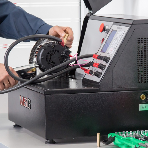
Test each alternator and bus individually where the architecture allows, then test the combined system. Verify polarity, protection, isolation, cable support, belt alignment, connector functions, and battery condition before starting. Use a load bank or controlled vehicle loads with defined limits.
Record output, regulation, ripple, voltage drop, temperature, and belt behavior for each unit at defined speeds and loads. The load-output verification procedure provides a useful measurement framework. Compare individual behavior before enabling parallel or cross-connected operation.
Individual performance evidence helps separate alternator capability from sharing and vehicle-control problems.
Increase load in stages and record each alternator current, bus voltage, battery current, voltage drop, engine speed, temperature, and control state. Repeat at hot idle and the approved higher speed. Confirm no cable, terminal, protection device, or belt exceeds its limit.
Use only an approved method to simulate a disabled alternator, open charge path, failed sense lead, or isolated bank. Confirm warning behavior, protected load shedding, remaining capacity, and recovery. Never disconnect a high-current cable from a running system as an informal test.
Provide a diagram showing alternators, batteries, buses, protection, grounds, sense points, communication, isolation devices, and major loads. Add normal voltage and current ranges for common operating modes. Place a controlled copy in the vehicle and service system.
Mark approved measurement points, required instruments, personal protective equipment, isolation sequence, and conditions for stopping the test. High-current battery systems can produce severe arc and fire hazards.
If regulation, idle speed, load shedding, or communication depends on vehicle software, record version, configuration, and change history. A hardware replacement may require calibration or coding to restore the intended sharing strategy.
Alternator capacity and battery architecture must be designed together. Identify battery chemistry, nominal voltage, capacity, allowable charge rate, temperature compensation, state-of-charge monitoring, isolation devices, and which loads may remain active with the engine stopped. Mixed battery banks require an approved charging strategy.
In split systems, one bank may reach target voltage while another remains low. In combined systems, different cable paths or battery conditions can create unequal current. Measure bank voltage and current during bulk, absorption, and steady operation where applicable. Do not use a simple combiner if the battery and charging specifications do not support it.
Classify loads as safety-critical, mission-critical, deferrable, or discretionary. Define voltage, current, temperature, or fault conditions that trigger shedding, and specify the restoration sequence. A dual alternator system should fail predictably rather than allowing every load to remain connected until the entire bus collapses.
Contactors, isolators, DC-DC devices, and combiners must handle continuous current, inrush, fault current, temperature, and switching duty. Confirm coil-control behavior and failure mode. Inspect heat and voltage drop under the maximum expected current, not only at idle with minimal load.
Temporary data logging during commissioning can reveal behavior that a handheld meter misses. Record bus and bank voltages, each alternator current, battery current, engine speed, temperatures, control state, and major load events. Align the timestamps so a voltage change can be connected to a fan, heater, inverter, or protection action.
Define expected ranges for idle, road speed, high-load body operation, battery recovery, and hot soak. Include acceptable current-sharing difference and maximum voltage drop. Technicians can then identify drift before the vehicle reaches a no-charge condition.
An alarm should indicate a condition and response: low bus voltage, excessive alternator temperature, sharing imbalance, open sense circuit, protection trip, or battery-bank divergence. Avoid alarm thresholds that trigger continuously during normal short transients, because operators will learn to ignore them.
When one alternator is disabled, confirm the remaining system supports the defined critical loads for the required time. If every failure still stops the vehicle, the second unit is providing capacity but not redundancy. That distinction should be clear in fleet expectations and maintenance plans.
For repeat B2B orders, retain approved alternator references, drawings, output curves, regulator and communication requirements, pulley and mount data, labels, serial or batch traceability, and paired test results. If units must be matched, define the matching tolerance and replacement policy.
Traceable units, labels, and test records support repeat procurement for controlled dual-alternator systems.
Decide whether one failed alternator may be replaced independently, whether regulators or software must match, and whether the remaining unit must be tested. Keep approved supersession rules. A new unit with a different regulation characteristic can upset a previously balanced pair.
Record failures by alternator, belt drive, cable, protection, battery, control, cooling, and installation. Measure downtime and whether redundancy actually preserved operation. The data should refine stocking, inspection, and architecture decisions.
A successful dual alternator system begins with a defined architecture and a time-based load model. It controls mechanical drive, current sharing, voltage sensing, protection, grounds, batteries, cooling, and failure response. Selection and diagnosis must use system evidence rather than treating each alternator as an isolated part.
Fleet and B2B buyers can send a dual-alternator load and wiring package with the vehicle, engine, voltage, load scenarios, battery banks, existing diagram, mount and pulley data, target capacity, operating environment, and quantity. That information supports a technically defensible aftermarket solution and shows whether a single high-output unit, split system, or parallel architecture is the better path.