ELECDURA NETWORK

Your Whole New Supply Chain For Heavy-Duty Parts
Whatsapp:
+86 18915027366
Phone:
+86 18915027366
Views: 0 Author: Site Editor Publish Time: 2026-07-22 Origin: Site
A heavy-duty alternator should be selected from the vehicle’s real electrical duty, not from a simple total of fuse ratings or accessory nameplates. List continuous loads, duty-cycled loads and short peaks; measure representative current at idle and operating speed; account for battery recovery, temperature, pulley ratio and future additions; then compare the resulting demand with the alternator’s speed- and temperature-dependent output curve. The chosen unit must cover the sustained worst credible condition with an explicit reserve while remaining mechanically and electronically compatible.
This method is a planning framework, not a universal amp formula. The vehicle, alternator and battery manufacturer data governs final selection.
Separate scenarios such as cold start recovery, night idle, urban delivery, highway cruise, PTO operation, emergency lighting, refrigeration, sleeper loads and accessory use with the engine off. A fleet may have adequate cruise output but discharge batteries during long idle periods. Build the budget around the scenario that creates sustained risk, not the single largest accessory.
Load class | How to record it | Planning treatment |
|---|---|---|
Continuous | Measured current in the scenario | Count the full representative value |
Duty-cycled | Current and on-time percentage over a defined interval | Use average for energy and peak for wiring/control checks |
Short peak | Magnitude and duration | Check transient voltage and battery support |
Battery recovery | State of charge, temperature and target recovery time | Add only with a stated charging objective |
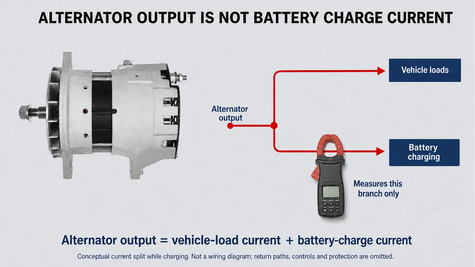
Measure the correct branch. Battery charge current is not the same as total alternator output or total vehicle load.
Fuse values protect circuits and normally exceed operating current. Nameplate values may describe maximum, nominal or test conditions. Use a calibrated clamp or shunt at identified branches and log current after the system stabilizes. Record engine speed, alternator speed if available, voltage, battery state, ambient or under-hood temperature and which loads are active.
Draw the charging path from alternator to junctions, batteries and major load branches. State where each reading is taken. Parallel cables, dual battery banks, battery isolators, smart distribution modules and auxiliary systems can cause one clamp location to miss part of the current.
Air-conditioning clutches, electric fans, heaters, pumps and aftertreatment devices cycle. Log long enough to capture their on and off periods in the real scenario. Preserve both the average demand and the simultaneous peak combination.
For each scenario, sum representative continuous loads and the time-weighted contribution of duty-cycled loads. Then state the battery-recovery allowance and reserve separately. Keeping those layers visible prevents the reserve from being counted twice and makes later accessory changes auditable.
Budget line | Night-idle example method | Evidence required |
|---|---|---|
Base vehicle | Measured stabilized current | Branch log and active systems |
Lighting and HVAC | Measured with defined duty cycle | On-time percentage and peak |
Auxiliary equipment | Measured or validated specification | Installation and control state |
Battery recovery | Target charge current for stated condition | Battery type, state and temperature |
Reserve | Chosen percentage or amp value | Fleet rationale and expansion plan |
Do not copy example values into a vehicle specification. The purpose of the table is to show the evidence fields and arithmetic structure.
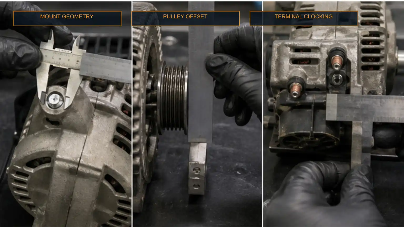
Electrical capacity does not authorize a replacement. Mounting, pulley and control interfaces must also match.
Rated alternator output is normally associated with defined speed and temperature conditions. Obtain the approved output curve and compare the load budget at the alternator speed produced by each operating scenario. Check hot performance, not only a cold bench rating. If the vehicle spends hours at idle, idle-speed output and cooling deserve more weight than maximum amp rating.
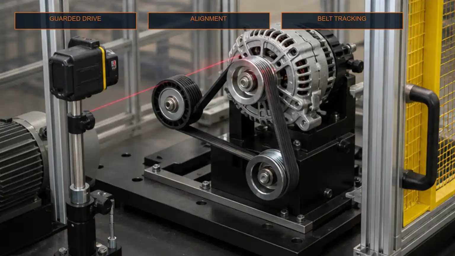
Calculate alternator speed from engine speed and the effective pulley ratio using approved diameters. Confirm maximum alternator speed at governed engine speed, belt wrap, tensioner capacity, bearing load, alignment and any one-way pulley requirement. Changing pulley size to improve idle output can create over-speed or drive problems.
A higher-output unit still requires belt, alignment, thermal and charging-control verification.
Confirm system voltage, regulator strategy, remote sense, lamp or field terminals, network communication, battery chemistry, cable capacity, protection and ground path. A replacement with sufficient theoretical output can still undercharge, overcharge or set faults if its control interface differs.
Repeat the priority scenarios after installation. Record voltage and current at the same measurement points, battery state, speed, temperature, belt behavior and warning status. Confirm that cables and terminals remain within their applicable temperature and voltage-drop limits. The release must show that the vehicle meets the defined load without hiding a battery, wiring or control problem.
Existing alternator label, references and output curve if available
Vehicle, engine and duty-cycle scenarios with measured load logs
System voltage, battery type and charging-control architecture
Mounting, pulley, rotation, terminals, rear clearance and cooling evidence
Required reserve, sample test plan and post-install acceptance record
The 24-volt alternator guide covers fitment and interface controls. Buyers can review available heavy-duty alternators before sending the completed load and fitment packet.
No. Fuse ratings are protection values and can substantially exceed real simultaneous current. Measure representative operation.
There is no universal percentage. State the fleet’s idle time, temperature, battery recovery, accessory growth and risk tolerance, then validate against the output curve.
No. Idle and hot output, pulley ratio, control compatibility, cabling, cooling and mechanical fitment are equally important.