ELECDURA NETWORK

Your Whole New Supply Chain For Heavy-Duty Parts
Whatsapp:
+86 18915027366
Phone:
+86 18915027366
Views: 0 Author: Site Editor Publish Time: 2026-07-22 Origin: Site
An alternator wiring diagram shows how charging current reaches the batteries, how the return circuit is completed, and how the regulator receives sensing or control information. On a heavy-duty truck, B+, ground, remote sense, ignition enable, warning-lamp and data connections perform different jobs. They must not be connected by matching wire colors or copying another alternator's connector layout. Identify the fitted alternator and vehicle electrical system first, then use the corresponding wiring documentation. A functional diagram helps explain the circuit; only the correct application diagram establishes where each wire belongs.
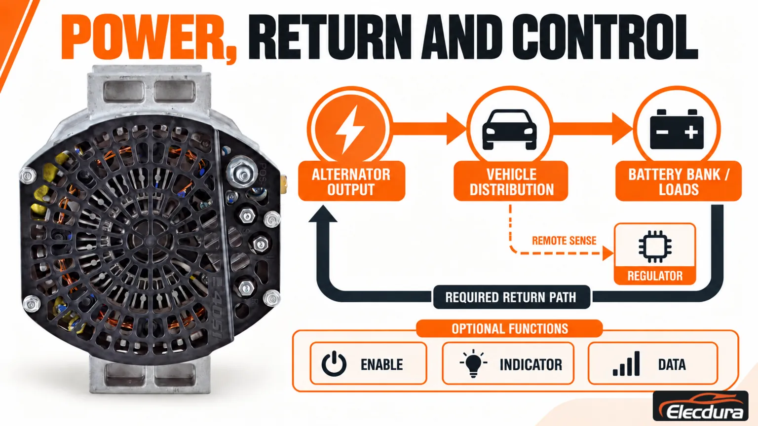
Separate the diagram into power delivery, the return path, voltage feedback and control signals. This prevents a small sensing wire from being mistaken for a charging feed or an indicator connection from being treated as an ignition supply.
Charging path: Alternator output connects through the vehicle's specified distribution and protection arrangement to the battery bank and electrical loads.
Return path: Current returns through the designated negative connections, which may involve the housing, engine bonding or a dedicated return terminal.
Voltage feedback: A remote-sense connection, where fitted, reports voltage at a designated battery or distribution point to the regulator.
Control and indication: Enable, warning-lamp, status and communication circuits perform the functions defined for that regulator and vehicle.
This is a conceptual circuit map, not an installation drawing. Some systems omit individual connections, combine functions or use different control arrangements. Battery isolators, auxiliary banks and converters must be represented where actually fitted; they cannot be assumed from the number of batteries alone.
Power, return and control are shown by function; terminal assignments require the matching vehicle documentation.
The following table describes functions, not universal pin assignments. Even a familiar letter must be checked against the exact alternator documentation and the vehicle connector drawing.
Circuit function | Markings or arrangements you may encounter | What must be confirmed |
|---|---|---|
Charging output | B+, BAT or + on applicable designs | The output terminal, cable route, distribution points and protection specified for the vehicle. |
Negative return | B-, GRD, a negative stud, or a designated housing connection | Whether the unit uses case grounding or an insulated return. A mounting bracket is not automatically the electrical return. |
Remote voltage sensing | S or a dedicated sense label on some designs | The actual sense terminal and monitored location. The letter S alone is not a universal definition. |
Ignition or enable | IG, I or another manufacturer-defined connection | Whether a switched supply or other enabling signal is required and how the vehicle provides it. |
Warning lamp or excitation | L or a design-specific lamp circuit | Whether the connection operates an indicator, participates in excitation, or has another documented function. |
Digital communication | LIN or another identified interface | The regulator's protocol and vehicle compatibility. This is not a terminal for an improvised battery feed. |
Status or phase output | DFM, R or W on particular alternator families | The documented signal and intended receiver. These labels do not describe interchangeable outputs. |
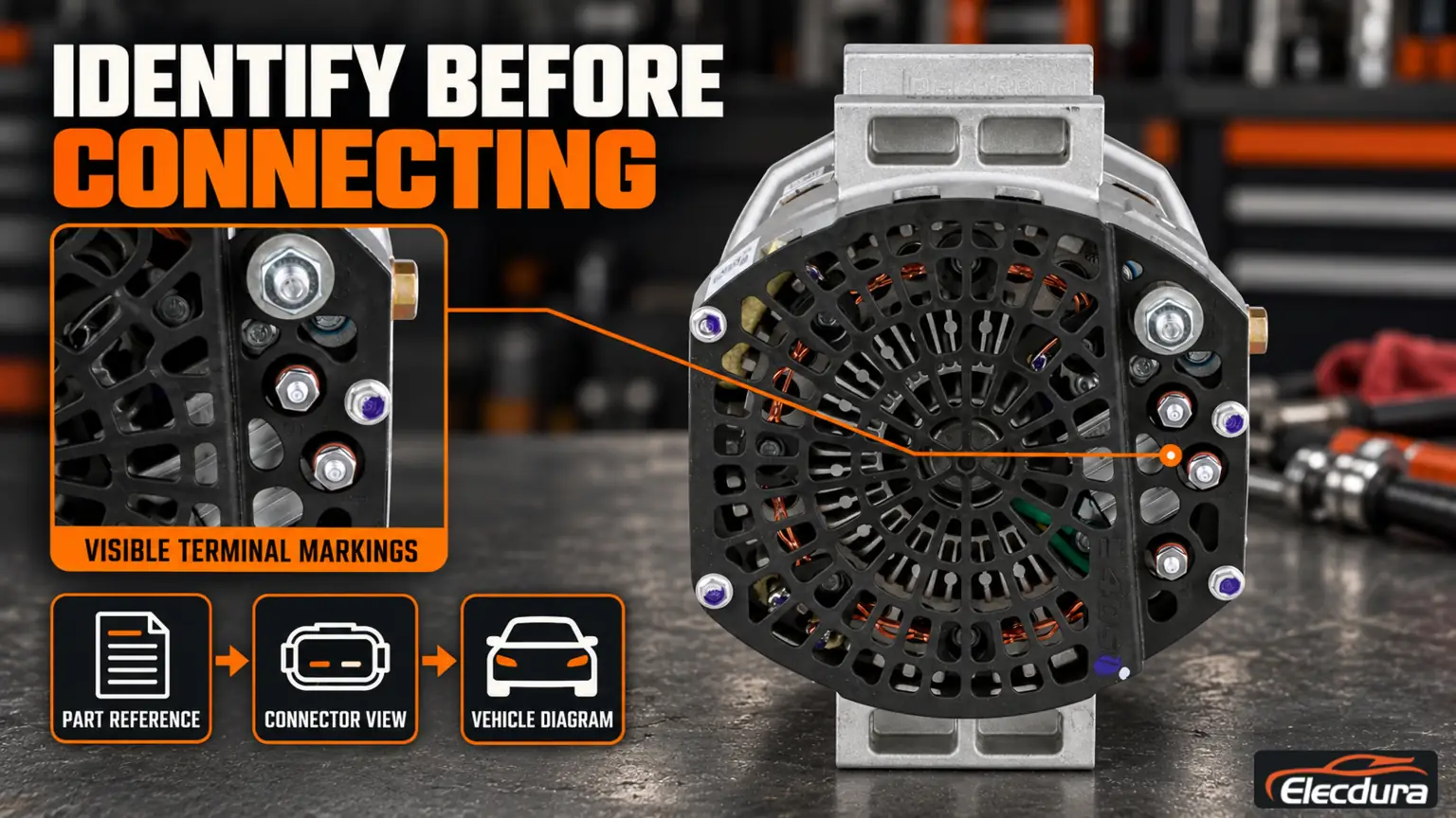
Connector cavities can also look mirrored when viewed from the harness side rather than the component side. Check the drawing's viewing direction and cavity numbering before comparing photographs. Pin count and plug shape help identify a unit but do not establish electrical compatibility.
Record the vehicle and engine identification, fitted alternator reference, nominal system voltage and battery arrangement. Photograph the label, rear connections and installed cable routing before any authorized disconnection. Keep unreadable or unconfirmed connections marked as unknown rather than assigning a function by appearance.
Obtain the vehicle wiring diagram together with the alternator manufacturer's terminal description. The first shows the harness and connected devices; the second identifies the alternator interface. They must agree with the actual equipment, including any documented conversion or replacement.
Where the correct pinout is unavailable, stop before applying power, moving wires or repinning the connector. Continuity, wire color and a key-on voltage reading cannot establish an unknown circuit's intended function. Circuit-specific testing may require approved adapters, an oscilloscope or scan-tool information, not merely a multimeter.
Electrical work belongs with qualified personnel. Follow the vehicle's isolation procedure for all relevant batteries and auxiliary supplies before disturbing connections. An alternator output or sensing lead can remain live with the engine stopped. Never disconnect the battery while the engine runs as a charging test.
Identify the part and obtain the corresponding connector view and vehicle diagram before connecting it.
A battery voltage reading does not locate a charging fault. First establish battery condition and inspect the belt drive and electrical connections. Then compare readings taken under the same manufacturer-specified operating conditions, with safe access arranged before the test.
Voltage loss in a charging cable, junction, fuse connection or return path can prevent the battery from receiving the intended charge. A loaded voltage-drop test assesses loss along the identified path while current flows. An unloaded continuity check can miss a connection that becomes restrictive under load.
Assess positive and return paths separately using the designated reference points. Do not substitute the housing for an insulated negative terminal. Record the load and operating condition, and compare results with the applicable limits. A small voltage drop with little current does not prove that the circuit can carry its required load.
Continue with the documented sense, enable, lamp or communication checks. Missing charge can result from an absent enabling signal, an incompatible regulator or an internal alternator problem. A warning lamp or communication code narrows the investigation but does not identify a failed alternator by itself.
On electronically managed systems, review the requested charging behavior and relevant faults before interpreting changing voltage as instability. Do not probe a data circuit with a powered test lamp or apply battery voltage to an unidentified small terminal.
Remote sensing lets a compatible regulator respond to voltage at a specified point away from the alternator. It can compensate for normal charging-path losses, but it does not repair a damaged cable or make an undersized connection acceptable. The response to an open sense wire varies by regulator; do not assume every unit will stop charging or overcharge.
An excitation or enable circuit has a different role. Some designs need an external start-up signal; others use self-excitation or electronic commands. A lamp circuit may participate in this process, but its function must be established from the correct diagram. Never join sense, ignition and lamp terminals merely to make the alternator begin charging.
For the regulator's role beyond wiring identification, see the alternator voltage regulator guide. The correct connector is only one part of matching the charging-control system.
Not without an approved cross-reference confirming the electrical arrangement. Matching housings and pin counts can conceal different terminal functions or regulator controls. Compare both part references with their terminal descriptions and the vehicle harness diagram before connecting the replacement.
Only when the instructions for that exact configuration explicitly require it. Moving the sensing point changes what the regulator measures and may defeat the intended compensation for cable loss. Do not use a jumper to hide a wiring fault or copy a connection from another model.
Some designs use the housing as part of the return path, while insulated-return units require the designated negative connection. Confirm the design and assess the specified return path under load. Secure mounting and a clean-looking bracket do not prove that the electrical return is correct.
Compare the original and replacement regulator interfaces, indicator circuit and any communication requirements. Check relevant vehicle faults and confirm that charging meets the application specification. Generating voltage does not prove that the lamp or data interface is compatible; do not silence the warning by disconnecting it.
Compare candidate heavy-duty alternators using the original reference, vehicle and engine details, system voltage, regulator interface, mount and pulley. Include clear connector photographs and the relevant wiring information where available.
For an application-based inquiry, send those details and the required quantity through the Elecdura contact page. Identify unresolved connections before ordering; neither a photograph nor a shared amperage rating confirms compatibility.