ELECDURA NETWORK

Your Whole New Supply Chain For Heavy-Duty Parts
Whatsapp:
+86 18915027366
Phone:
+86 18915027366
Views: 0 Author: Site Editor Publish Time: 2026-07-23 Origin: Site
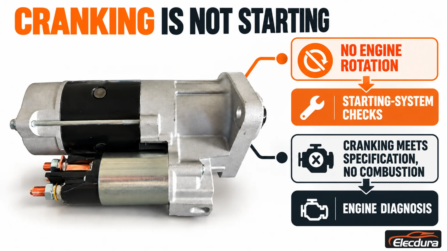
A heavy-duty starter replacement is complete only when the unit matches the engine's mechanical, electrical and control requirements and the installed system passes its cranking checks. A starter that bolts into place can still have the wrong pinion, return circuit or control interface. Before ordering, distinguish an engine that does not crank from one that turns at the required speed but does not start. The second condition calls for engine no-start diagnosis, not automatic starter replacement. Preserve the original installation details, correct related faults and verify engagement, cranking performance and release after fitting.
Describe what the engine actually does, not simply that it "will not start." Starter noise and engine rotation are different observations. Confirm cranking performance against the engine requirement rather than judging speed by ear.
Observed condition | What it means for replacement | Next action |
|---|---|---|
No engine rotation, with or without a click | Battery supply, control, cables, starter or mechanical resistance may be involved. | Complete the applicable starting-system checks before condemning the unit. |
Engine rotates too slowly | Insufficient cranking performance is confirmed only against the specified conditions. | Assess batteries, cable losses, starter performance and engine resistance together. |
Starter spins but the engine does not rotate | The motor running does not prove successful drive engagement. | Inspect the drive, pinion, ring gear and installation geometry. |
Engine cranks at the required speed and voltage but does not fire | The complaint is not, by itself, evidence that another starter is needed. | Follow engine diagnosis for fuel delivery, compression, timing and control authorization as applicable. |
Grinding or starter operation continues after starting | Engagement, release, control or mechanical damage needs attention. | Stop further operation as required and investigate before returning the vehicle to service. |
Obtain the diagnostic findings before ordering. Where only a separately serviceable solenoid is defective, the starter solenoid replacement guide covers that narrower repair. A complete unit should not be used to bypass an unresolved cable or control fault.
Starting-system checks and engine diagnosis address different symptoms.
Photograph the label, mounting flange, pinion area, solenoid orientation, terminal markings, cable routing, braces and heat shields. Record any spacer, gasket or shim and its location. Note contamination, damaged insulation and unusual wear before cleaning removes those clues.
Retain the old starter until the replacement configuration is resolved and post-installation checks are complete, subject to agreed return arrangements. It provides useful comparison material, but a previous incorrect part or installation must not become the specification for the new unit.
Use vehicle and engine identification together with the approved replacement reference. If the label, catalog information and installed interfaces disagree, resolve the discrepancy before modifying anything. A documented supersession may legitimately change external appearance; visual similarity alone proves neither compatibility nor incompatibility.
Starter removal provides access for inspecting the ring gear. Qualified personnel should check its full circumference using the engine manufacturer's safe positioning procedure, not just the teeth visible in one position. Damage may be localized, and a new starter cannot restore a worn or broken ring gear.
Assess teeth, mounting surfaces and associated components against the applicable service criteria. Grinding or pinion damage also warrants review of the previous installation and engagement geometry. Correct confirmed faults before exposing the replacement to the same conditions.
Mechanical matching must include:
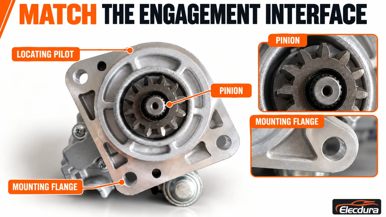
Mounting flange, locating pilot, bolt pattern, specified fasteners and support-bracket provision.
Pinion tooth count and profile, diameter, rest position and the approved relationship to the ring gear.
Direction of rotation using the reference viewing direction defined by the manufacturer.
Nose or noseless construction, installed clearances and solenoid orientation.
Any required gasket, spacer or application-specific shim arrangement.
Do not add washers as spacers, grind a housing or use mounting bolts to pull a misaligned unit into position. Shim requirements vary: some installations require a specified spacer, while particular replacement housings are designed for no-shim installation. Apply the instructions for the actual engine and replacement, not a rule copied from another starter family.
Check the complete engagement and mounting interface for the specified application.
Check system voltage, specified starter performance and the battery arrangement. A shared model-family name or nominal power rating does not establish that the replacement suits the engine.
Confirm whether the design returns current through its housing or a dedicated negative terminal. An insulated-return starter requires its designated connection; bolting it to the engine does not substitute for that cable. Inspect the vehicle's battery interconnections and bonding paths as part of the installation.
The control interface is equally important. Identify any attached magnetic relay, electronic switching or over-crank protection and compare its required operation with the vehicle circuit. An integrated magnetic switch and the main solenoid are not automatically the same component, and different control variants may require different connections.
Tag leads by their confirmed functions, not only their old physical positions. Terminal locations may differ on an approved replacement. Do not bridge protection connections or bypass start interlocks to make an incompatible unit operate.
The work belongs with qualified personnel following the vehicle and starter instructions. Secure the vehicle against movement, control raised bodies or attachments where relevant, prevent automatic starting, allow hot components to cool and isolate all relevant power supplies before disturbing cables.
Plan access and support the starter with suitable handling equipment. Do not suspend it by its wiring or rely on the last mounting bolt to carry unsupported weight. Protect adjacent hoses and harnesses throughout removal and installation.
Confirm the mounting surfaces and hardware, then seat the replacement correctly and restore required braces, shields and seals. Follow the specified tightening sequence and values. Drain orientation, where applicable, is part of the installation rather than a cosmetic choice.
Electrical connections need clean contact surfaces, correct insulation and cable support. Route cables with allowance for engine movement and clearance from exhaust heat and moving parts. A cable lug must not twist a terminal stud, carry the cable's unsupported weight or contact the housing. Recheck the completed installation before restoring power.
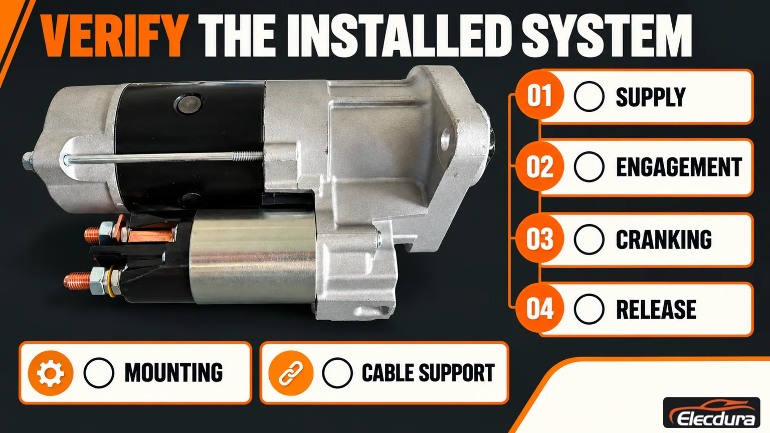
A bench report describes a component under its stated test conditions. Vehicle acceptance confirms that the replacement works with the battery bank, wiring, controls and engine load. Use the relevant service procedure and keep the before-and-after conditions comparable.
Acceptance item | What to record | What the result does not establish alone |
|---|---|---|
Battery supply and return | Battery condition, voltage during the approved start event and specified positive/negative path checks. | An acceptable resting voltage does not prove adequate supply during cranking. |
Control response | Start authorization, identified control input and required protection behavior. | A relay click does not prove that the complete control path operates correctly. |
Engagement and engine rotation | Cranking speed, relevant current measurement where prescribed, engagement behavior and abnormal noise. | Motor rotation alone does not prove the engine is being driven correctly. |
Disengagement | Correct release after the command ends or the engine starts, according to the design. | One successful start does not rule out intermittent run-on. |
Complaint-specific verification | Results under the relevant cold or warmed-up conditions where safely reproducible. | A cold workshop pass does not resolve an exclusively heat-related complaint. |
Arrange approved test equipment safely before operation and keep clear of moving parts. Respect the starter's duty and cooling limits. Never prolong cranking to compensate for an engine that will not fire or use improvised terminal bridging as an acceptance test.
If performance remains abnormal, interpret voltage, current and speed together. High current with low speed can involve either starter inefficiency or engine resistance; low current does not independently identify a bad cable. Compare the complete result with the specified conditions before replacing another component.
When cranking meets requirements but combustion still does not begin, stop treating the job as a starter-parts problem. Follow the engine diagnostic route. Keep the cranking record so the next technician can see what was actually verified.
Verify the installed system using the application-specific acceptance procedure.
Only if testing also identifies a starting-system defect. Verify cranking speed and voltage rather than relying on sound. When they meet the engine requirement, investigate the engine's fuel, compression, timing and control conditions instead of assuming a different starter will make it fire.
Not on those details alone. Gear profile, mounting geometry, installed pinion position, rotation, output and control connections also matter. Use an approved application match; any differences in a replacement design need documented support rather than modification by trial and error.
Record every removed spacer or shim, then check the engine and replacement instructions. Required original spacers must not be omitted, but no-shim designs and other applications may differ. Do not invent a universal gap or add shims solely to silence grinding without finding its cause.
Yes. The bench cannot establish the condition of the vehicle's batteries, cable paths, ring gear or control wiring. Confirm the installed engagement, cranking and release behavior using the applicable procedure, and record the conditions so later complaints can be compared fairly.
Stop further start attempts and follow the vehicle's safe shutdown procedure. Inspect the part match, mounting, ring gear, drive and control release. Do not continue cycling the starter to see whether it settles in, and do not assume that a new unit rules out installation or vehicle faults.
For heavy-duty starter sourcing, provide the original reference, engine and vehicle identification, system voltage, mounting and pinion photographs, return-path and control requirements, quantity and confirmed fault. Include documented supersessions and required accessories.
Submit the information through the Elecdura contact page for application review. Confirm compatibility and availability before ordering, and retain the selected reference with the installation and cranking records.