ELECDURA NETWORK

Your Whole New Supply Chain For Heavy-Duty Parts
Whatsapp:
+86 18915027366
Phone:
+86 18915027366
Views: 0 Author: Site Editor Publish Time: 2026-07-25 Origin: Site
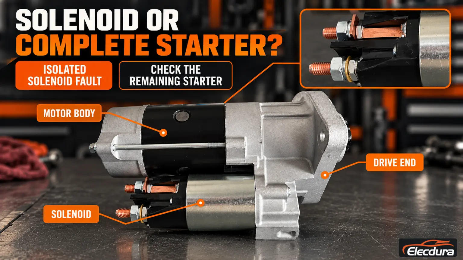
Starter solenoid replacement is appropriate when the fault has been isolated to a separately serviceable solenoid and the remaining starter meets its inspection requirements. It is not a cure for weak batteries, cable losses, damaged gears or a worn motor. The replacement must match the starter's electrical design, plunger and linkage geometry, terminal insulation and control arrangement. After fitting, the complete starter needs the prescribed functional checks, followed by verification in the vehicle. This guide addresses that repair decision and matching process, rather than treating a click or an intermittent start as proof that a solenoid should be changed.
Begin with the completed diagnosis: which component failed, under what conditions, and what else was inspected? Retain the findings rather than repeating tests until one result appears satisfactory. If the fault is not yet isolated, use the starter solenoid testing guide before deciding the repair scope.
Confirmed condition | Reasonable repair direction | What must not be overlooked |
|---|---|---|
Solenoid fault; motor, drive, bearings and housing remain serviceable | Consider an application-matched solenoid or approved service kit. | The manufacturer must support that repair and the workshop must complete the required checks. |
Motor or drive damage accompanies the solenoid fault | Assess a broader overhaul or complete starter replacement. | A new switch does not restore damaged windings, bearings or drive components. |
Battery, cable or control fault remains unresolved | Correct the vehicle-side fault and reassess the starter. | Replacing a solenoid alone may leave the cause of chatter or poor engagement in place. |
Damaged pinion or ring gear | Inspect the engagement system and correct out-of-specification components. | Neither a new solenoid nor a new starter repairs a damaged engine ring gear. |
Correct service parts or repair instructions cannot be established | Obtain specialist identification or evaluate a verified complete replacement. | Do not adapt an unknown plunger or improvise an electrical connection. |
Neither age nor appearance establishes the repair boundary. A limited fault can justify component replacement; multiple failures may make it unsuitable. The decision belongs to the inspected unit, not to an assumed rule that replacing the smaller part is always preferable.
Confirm whether the fault and serviceability justify solenoid repair or complete starter replacement.
On many pre-engaged starters, the main solenoid operates the shift mechanism and switches motor current. Some heavy-duty starters also have an attached integrated magnetic switch, commonly abbreviated IMS, which serves a relay function. Other designs integrate functions differently. Identify the actual assembly before ordering a part described simply as a "starter switch."
The starter family name narrows identification but does not specify every voltage, linkage or control version. Use the complete starter reference, any solenoid reference, application information and the manufacturer's service-parts listing. Preserve suffixes and documented supersessions.
The removed unit is a useful reference, not unquestionable authority. Previous repairs may have fitted the wrong component. Resolve disagreements between the old part, service listing and vehicle requirements before approving the replacement.
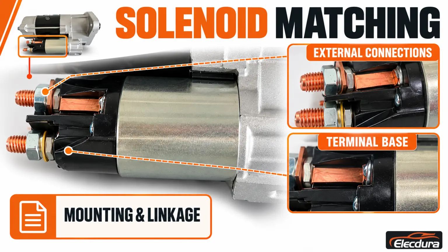
A solenoid can fit its mounting holes yet be unsuitable for the starter. Compare the following items against the exact service specification:
Voltage and coil arrangement: the specified control supply, pull-in and hold-in design where applicable, and return connection.
Plunger and linkage: length, connection shape, travel, spring arrangement and their relationship to the shift lever.
Mounting and orientation: fixing pattern, installed position, sealing and clearance around the starter and vehicle.
Contacts and terminals: documented functions, current-path design, stud dimensions and connector arrangement.
Insulation: the correct sleeves, washers, terminal barriers and motor-strap isolation.
Associated equipment: required relay, protection circuit, suppression components and terminal shields where fitted.
Correct nominal voltage is necessary but insufficient. An unsuitable plunger or linkage can prevent the intended contact closure or drive movement. A terminal placed differently can also leave a cable strained or dangerously close to the housing.
Do not assign battery, motor or control functions by stud size. Confirm them from the applicable terminal drawing. Likewise, do not assume that a protection function can be removed merely because the replacement has fewer wires.
Match the electrical interfaces and verify the specified mounting and linkage.
Replacement should be performed by qualified personnel. Secure the vehicle against movement, prevent automatic or unintended starting, and isolate all relevant electrical supplies according to the vehicle procedure. If the starter must be removed, support its weight with suitable equipment; cables and terminal studs are not lifting points.
Before disassembly, photograph the connections, solenoid position and accessible linkage details. Clean external contamination without introducing it into the assembly. Keep springs, clips, boots, seals and insulating parts identified with that starter rather than mixing similar pieces from several repairs.
Inspect disturbed components against their service criteria. Heat-damaged insulation, a binding linkage or an unsuitable return spring must not be hidden by fitting a new solenoid. Reuse, replacement and lubrication requirements come from the actual repair instructions; do not apply arbitrary grease or substitute insulating washers.
Use the specified hardware arrangement and tightening procedure without twisting studs, conductors or the motor strap. A photograph records what was removed, but the approved instructions determine what should be reassembled.
Solenoid service procedures are not interchangeable. Some designs require a defined pinion-clearance check or adjustment after replacement; others use a different linkage and service method. Never import a clearance, shim arrangement or powered adjustment sequence from another starter family.
Any required powered test belongs on an approved, secured and guarded setup operated by trained personnel. Do not bridge large terminals or energize a loose starter on a workbench. Follow the prescribed duty and cooling limits rather than repeating long cycles to search for an intermittent fault.
Acceptance area | What the repair must demonstrate | Important limitation |
|---|---|---|
Mechanical assembly | Correct linkage, specified travel or clearance, unobstructed movement and return. | Movement by hand does not prove electrical performance. |
Solenoid function | The required pull-in, holding, contact operation and release behavior. | An audible click does not prove that the current path is serviceable. |
Complete starter performance | Model-appropriate motor, drive and electrical checks under the prescribed conditions. | A free-running test alone does not establish installed cranking capability. |
Insulation and protection | Correct isolation of live parts and operation of required protective features. | Do not apply a generic insulation-test method to electronic components. |
Record the starter identity, replacement part, procedure used, test conditions and results. Engagement sequence must be judged against that design: a starter with controlled soft engagement need not behave like a conventional direct-drive unit.
Before reconnecting power, confirm mounting, cable support, insulation, terminal clearance and the specified return path. Restore the required shields and protective connections. The complete installation process is covered in the starter replacement and cranking acceptance guide.
Check engagement, cranking and release using the vehicle's procedure. If the original fault occurred after heat soak, include an appropriate warm-condition check when the approved procedure permits. A cold pass does not settle a complaint that has only occurred when hot.
If chatter, grinding or continued engagement remains, stop further start attempts as required and investigate. Review the supply, control, linkage and motor rather than fitting another solenoid without explanation. Keep the repair findings with the vehicle record for comparison if the complaint returns.
Yes, where diagnosis isolates the solenoid, the starter is otherwise serviceable and the design supports separate replacement. Confirm the service kit and required post-repair checks first. A confirmed solenoid fault does not automatically establish that the motor and drive are healthy.
Not necessarily. Coil arrangement, plunger geometry, terminal functions, insulation and control features must also match. Compare the complete references and service-parts information. Do not alter wiring or linkage to force a near match to operate.
Only where the applicable kit instructions permit reuse and the components meet inspection requirements. Some repairs specify replacement or a particular supplied combination. Similar length or appearance does not establish the correct travel or spring behavior.
No universal rule applies. Access, isolation requirements, linkage checks and the manufacturer's repair method determine whether removal is necessary. Do not choose an in-place repair solely to avoid removal when it prevents the required inspection or acceptance checks.
The remaining problem may involve battery supply, cables, the motor, engagement or an incorrect replacement. Compare the installed result with the original diagnosis and the exact starter procedure. A click confirms neither successful gear engagement nor adequate motor-current delivery.
Provide both starter and solenoid references, vehicle and engine details, voltage, label and connection photographs, the confirmed fault and required quantity. State whether the inquiry concerns a component-only repair or complete heavy-duty starters.
Send the information through the Elecdura contact page for application review. Component availability and compatibility require confirmation; this is not an offer of workshop repair services.