Views: 0 Author: Site Editor Publish Time: 2026-07-30 Origin: Site
The rotor and stator are the electromagnetic center of an alternator. The rotor creates a rotating magnetic field, the stator converts that moving field into multi-phase AC voltage, and the rectifier converts the result to DC for the vehicle. When charging output falls, technicians often replace a regulator or diode first. That can miss an open rotor field, shorted stator turn, phase imbalance, insulation breakdown, or mechanical runout that is producing the electrical symptom.
Elecdurauto supplies a heavy-duty alternator range for trucks, buses, diesel engines, construction equipment, agricultural machinery, and other severe-duty applications. High-output units operate under significant electrical, thermal, and mechanical stress, so rotor and stator evidence matters to fleets, rebuilders, distributors, and importers.
This guide explains how the two assemblies work together, how their failure patterns differ, and how to use field current, phase output, ripple, insulation, temperature, balance, and production records to make a controlled repair or sourcing decision.
Battery or regulator current enters the rotor field through brushes and slip rings or through another approved excitation arrangement. The energized rotor poles create a magnetic field. As the engine turns the rotor, the field crosses the stator windings and induces AC voltage in each phase. Diodes rectify those phases, and the regulator adjusts field current to maintain the system target.
Field current, rotor winding turns, pole geometry, air gap, speed, and magnetic condition determine field strength. An open field produces little or no output. A shorted field can change current demand, heat the rotor, and limit excitation. Poor slip-ring contact can make the field intermittent.
The stator windings carry the generated phase current. Conductor size, winding layout, connection, slot insulation, varnish, heat transfer, and phase balance affect output and durability. A shorted turn may still produce voltage with little load while overheating rapidly under demand.
A diode failure can remove or distort a phase, while a regulator problem can command too little or too much field. Rotor, stator, rectifier, regulator, battery, wiring, and load must therefore be tested as a system.
A high-output alternator depends on the rotor field, stator phases, cooling, rectifier, and regulator operating as one system.
A useful diagnostic question is whether the regulator is asking for field and whether the rotor circuit can carry that request. Measure only with the approved procedure because field access and control strategies vary. Compare command or field current with charging output, speed, voltage, temperature, and battery state.
If the system commands strong field but output remains low, investigate rotor field strength, stator phases, rectifier losses, speed, belt slip, and internal heat. The regulator may be responding correctly to a generation problem rather than causing it.
Check excitation supply, brushes, slip rings, rotor continuity, regulator command, warning-lamp or ignition circuits, communication, and grounds. An open rotor winding can look similar to a missing regulator command unless both sides are checked.
Compare winding resistance with the model and temperature specification. Very high resistance can indicate an open or poor connection; abnormally low resistance can indicate shorted turns. Test insulation to the shaft or core only with approved voltage and equipment so electronics are not damaged.
Copper resistance rises with temperature. Record rotor temperature and test method when comparing units or batches. A cold value should not be judged against a hot limit without compensation.
The rotor is an electrical winding on a high-speed rotating assembly. Mechanical condition therefore affects electrical durability. Inspect shaft journals, slip rings, poles, fan or attached components, bearings, runout, balance marks, and evidence of contact with the stator.
Look for grooves, burning, contamination, eccentric wear, high resistance, and loose connections. A poor brush track interrupts field current and can create arcing. Machining or replacement must remain within diameter, finish, concentricity, and insulation limits.
A bent shaft, worn bearing seat, incorrect bearing, or unbalanced rotor can reduce air-gap clearance and allow contact. Witness marks on the rotor or stator, metallic debris, and a changing mechanical sound require dimensional inspection before electrical release.
Pulley diameter, belt ratio, engine maximum speed, and rotor balance determine mechanical stress. A smaller pulley may improve idle output while increasing maximum rotor speed. Balance error adds bearing load and vibration that can damage windings and rectifier connections.
The stator should produce balanced phase behavior under the same magnetic field. Depending on access and design, diagnosis may compare phase voltage, phase resistance, current contribution, waveform, or temperature. Follow the alternator procedure and isolate electronics where required.
An open winding or connection reduces output and changes ripple. The alternator may still charge lightly because the remaining phases contribute. Under load, capacity and thermal balance deteriorate.
A shorted turn can be difficult to identify with a basic resistance meter because the total resistance is already very low. Look for reduced output under load, high stator temperature, localized discoloration, imbalance, waveform distortion, and results from approved surge or inductance testing.
Insulation failure between a winding and the core or housing can create leakage, heat, diode stress, electrical noise, or a direct fault. Inspect slot liners, lead exits, varnish, connections, contamination, and abrasion. Use the specified insulation test voltage.
Wye or delta junctions, phase leads, welded or soldered joints, and rectifier connections carry high current and heat. A loose or cracked joint may be intermittent with vibration and temperature even when a cold continuity check passes.
DC output contains a controlled amount of AC ripple. An abnormal waveform can indicate a missing phase, shorted or open diode, stator imbalance, or connection problem. A single AC-voltage number is less informative than waveform shape, load, speed, battery condition, and comparison with the model specification.
A regular repeated gap may suggest that one phase or its diode path is not contributing. Determine whether the winding is open, the connection is damaged, or the rectifier path has failed before replacing either assembly.
Brush interruption, loose connections, control instability, and electrical loads can create irregular ripple. Correlate the waveform with field current, mechanical speed, vibration, and temperature.
The battery smooths system voltage. A disconnected, damaged, or poorly connected bank changes ripple and regulator behavior. Test with the correct battery configuration and never disconnect batteries from a running heavy-duty charging system as a diagnostic shortcut.
Rotor, stator, rectifier, bearings, and terminals heat for different reasons. Measure temperature with a consistent method and under a recorded load, speed, ambient condition, and time. A thermal image or contact reading is useful when compared across similar points and repeated conditions.
Investigate excessive field current, shorted turns, poor ventilation, slip-ring resistance, mechanical contact, overspeed, and nearby heat sources. Determine whether the regulator is commanding high field because the stator or vehicle path cannot meet demand.
A hot phase area, lead joint, or slot can indicate shorted turns, poor connection, insulation damage, or uneven cooling. Discoloration and varnish odor support the finding, but a controlled electrical test is still required.
Investigate sustained overload, insufficient hot-idle output, blocked airflow, high ambient temperature, incorrect pulley ratio, belt slip, battery recovery demand, and under-capacity selection. A sound winding can be overheated by the application.
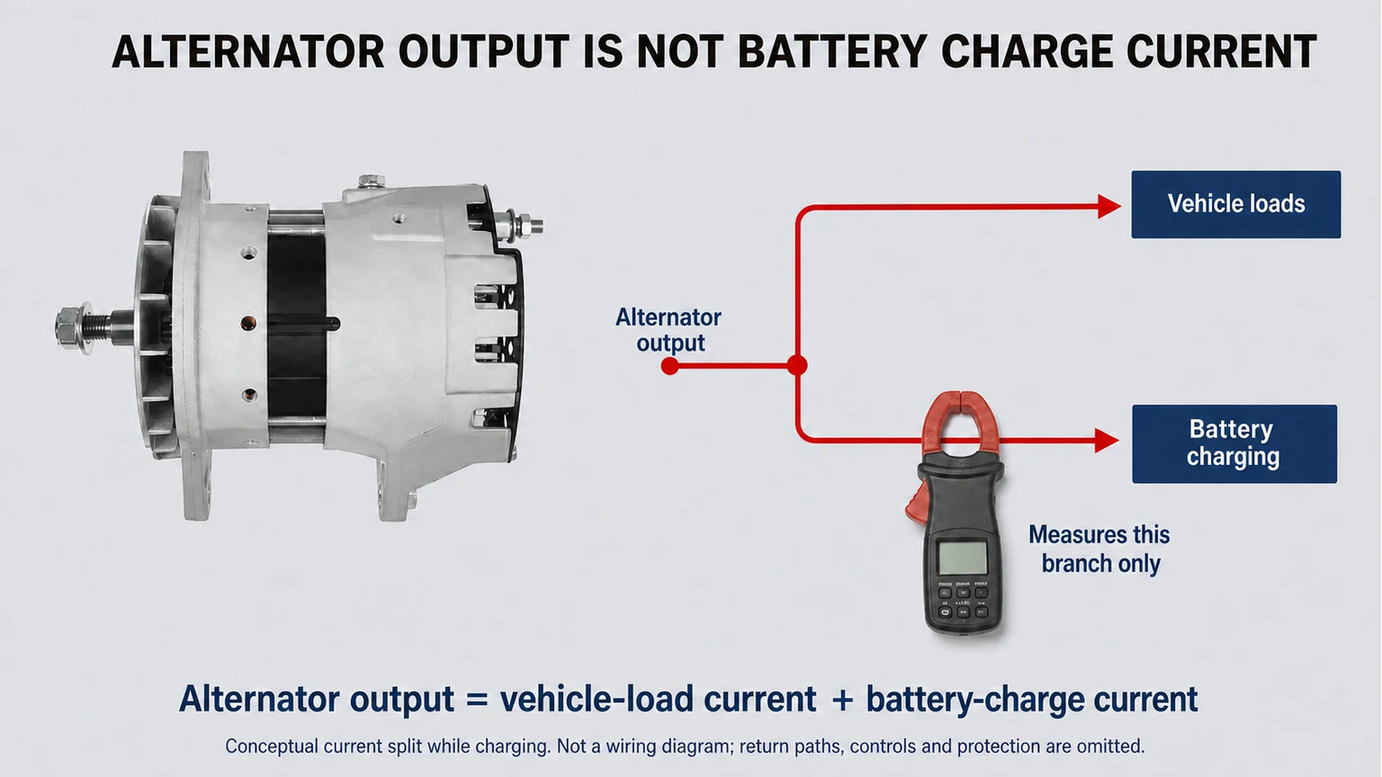
Start on the vehicle because wiring, battery, belt, loads, and control strategy affect the result. Record charging voltage, current, shaft or engine speed, electrical load, positive- and negative-side voltage drop, field behavior where available, ripple, and temperature. The alternator load-output testing procedure provides a system-level framework.
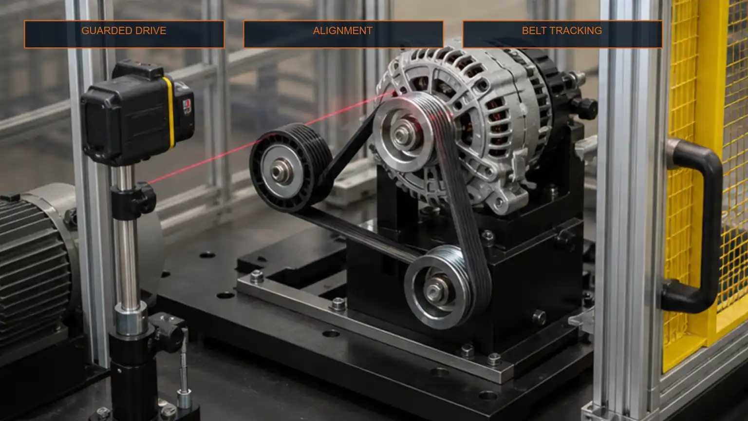
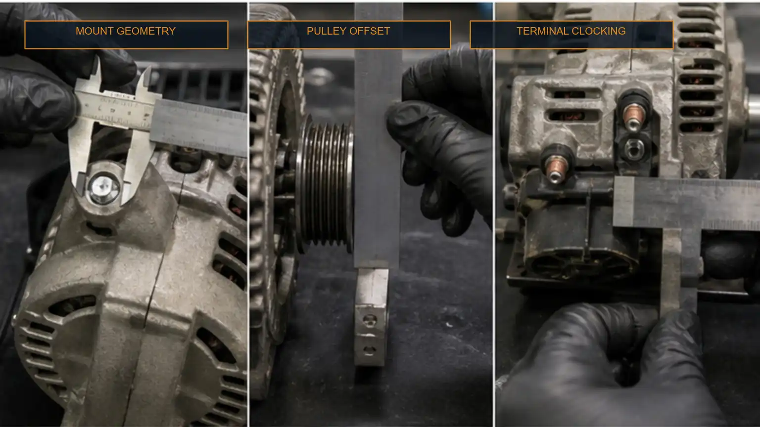
Remove the alternator when vehicle tests isolate an internal generation fault, when access prevents safe confirmation, or when mechanical noise and debris require inspection. Preserve the pulley, label, connector, and installation evidence so bench results can be connected to the application.
Inspect the exterior, pulley, shaft, bearings, terminals, and contamination before disassembly.
Test output, regulation, ripple, and temperature at defined speeds and loads.
Measure rotor field continuity, resistance, insulation, slip-ring condition, and runout.
Measure stator phase condition, insulation, connections, and evidence of localized heat.
Test rectifier and regulator separately only with approved methods and limits.
Repeat final performance testing after repair and retain the before-and-after data.
A rotor or stator repair should be evaluated against winding capability, core condition, process control, test capacity, downtime, and repeatability. Replacing one winding assembly may be economical in a controlled rebuild facility; a complete replacement may be safer for field service or when several systems have aged together.
Consider shaft and pole integrity, winding and connection repairability, slip-ring dimensions, bearing fits, balance capability, excitation design, and availability of a verified rotor. A rewound rotor needs resistance, insulation, runout, balance, and performance evidence.
Consider core condition, winding data, conductor size, connection, slot insulation, varnish process, lead routing, thermal class, impregnation, and test capability. A stator that looks clean can still contain a shorted turn or weak insulation.
Complete replacement may reduce downtime and interface uncertainty when the rectifier, regulator, bearings, housing, rotor, and stator all show significant service. The 40SI 12V 300A-320A alternator and 55SI heavy-duty alternator range show the importance of matching high-output duty, voltage, mounting, and cooling as a complete package.
Importers and distributors need evidence beyond a clean exterior. The approved sample should include winding and assembly specifications, critical dimensions, test curves, insulation results, balance records where relevant, thermal or endurance sampling, and change control. Batch inspection can then focus on the characteristics that drive field performance.
Review conductor size, turn count, phase layout, slot fill, lead routing, connection quality, slot insulation, varnish coverage, cure process, and traceability. Automatic equipment can improve consistency, but setup and inspection records remain essential.
Controlled winding placement supports phase consistency, insulation protection, and repeat production.
Review winding data, pole and shaft condition, connection integrity, slip-ring finish, runout, bearing fits, and dynamic balance. Balance should be tied to a defined limit and retained by lot or sample plan.
Dynamic balancing reduces vibration that can damage bearings, windings, and high-current connections.
Test output at defined speeds and temperatures, regulation, ripple, field behavior, efficiency where specified, noise, and thermal stability. Keep serial or batch traceability between the unit label, test record, packaging, and purchase order.
The A003TV9171A MAN truck alternator illustrates how an OE-reference and truck application can narrow matching. The reference should still be verified against voltage, output, mount, pulley, connector, regulator, and old-unit evidence.
Investigate speed, pulley ratio, sustained overload, battery demand, temperature, rectifier loss, and specification mismatch. The generating assemblies may be healthy but undersized for the duty.
Investigate stator winding, phase connection, and the corresponding rectifier path. Compare waveform, resistance or approved phase tests, and localized temperature.
Investigate brushes, slip rings, rotor connections, regulator command, excitation wiring, grounds, and control communication. Do not condemn the stator for output that changes with missing field.
Investigate expansion-related opens, insulation leakage, brush movement, rotor winding resistance, stator connection cracks, rectifier heat, and cooling. Repeat the test at the documented temperature and load.
Rotor and stator diagnosis becomes clearer when the energy path is measured. Confirm field command and rotor continuity, compare stator phases, inspect ripple and temperature, and rule out belt, battery, cable, regulator, and rectifier effects. Mechanical runout and balance belong in the same investigation because a high-speed electrical assembly cannot be separated from its rotating condition.
For repair and B2B sourcing, release the alternator only when winding, insulation, balance, phase, output, regulation, thermal, and traceability evidence agree. Buyers can send alternator test data for matching with the label, application, voltage, output, mount, pulley, connector, measurements, quantity, and required test standard.
Hot-Start Diesel Injector Return Flow and Rail Pressure Diagnosis
VGT Turbo Actuator Hysteresis and Vane Sweep Calibration Guide
Starter Motor Ground Circuit Voltage Drop Testing for Heavy-Duty Diesel Engines
Alternator Load Dump and Transient Voltage Protection for Heavy-Duty Fleets
Alternator Rotor and Stator Failure Guide for Heavy-Duty Charging Systems