ELECDURA NETWORK

Your Whole New Supply Chain For Heavy-Duty Parts
Whatsapp:
+86 18915027366
Phone:
+86 18915027366
Views: 0 Author: Site Editor Publish Time: 2026-08-21 Origin: Site
An alternator can produce acceptable average DC voltage while one diode or stator phase is failing. The missing or distorted portion of the rectified waveform raises AC ripple, reduces usable output, heats components, and can disturb batteries or electronic controls.
A single handheld reading is not enough unless meter bandwidth, connection point, battery condition, electrical load, engine speed, and temperature are controlled. Loose cables, poor grounds, discharged batteries, variable-frequency loads, and test-lead placement can change the apparent ripple. Buyers can use the Elecdurauto alternator category to organize reference and application research; final selection still depends on the measured application record.
This guide uses an oscilloscope and synchronized charging measurements to turn ripple into a repeatable diagnostic and replacement-acceptance record.
Ripple data should be retained as both a numeric measurement and a waveform image. The number supports threshold comparison, while the image preserves phase spacing, repeated notches, intermittent dropouts, and switching noise. Together they make the decision reviewable after the alternator has been removed.
For a bulk replacement program, the approved waveform can also serve as a receiving benchmark. Selected units are tested at the same speed, temperature, and load so a changed rectifier, winding, regulator, or assembly process becomes visible before installation.
Temperature matters because an intermittent rectifier joint or winding connection may appear normal during a short cold test. The acceptance sequence should include a stabilized hot point and retain the time required for the waveform to change. Repeatability across two load cycles gives the reviewer stronger evidence than one transient capture under real workshop conditions.
Confirm battery state, bank balance, nominal voltage, alternator identity, pulley ratio, belt condition, cable connections, controller status, and baseline DC voltage. Before testing, the technical buyer ties battery condition to a named vehicle, engine, or bench configuration. That record establishes a measurable starting point for the investigation and prevents a convenient no-load observation from defining the entire alternator case.
Establish battery condition first, then compare alternator identity while the original complaint is reproduced. Use drive speed to challenge the first interpretation and retain DC baseline as the condition that another workshop or supplier can repeat. Temperature, speed, load, connection point, and instrument identity belong beside every value.
The opening record must explain why battery condition represents the starting state and how alternator identity changes when the suspected failure appears. If evidence from drive speed points elsewhere, the diagnosis stays open. DC baseline becomes the reference used to compare the removed unit, approved sample, and later production lot.
Battery condition: Capture the initial value and the exact operating condition.
Alternator identity: Compare the response before and during the complaint.
Drive speed: Use an independent observation to test the first theory.
DC baseline: Preserve the reference with date, instrument, and reviewer.
Ripple interpretation starts with a stable system and correct alternator speed. A missing baseline cannot be recreated from memory after replacement, so unresolved fields remain marked pending. The first gate closes only when the complaint and the recorded alternator behavior describe the same event.
Document battery condition against the complaint, alternator identity, operating state, and named reviewer. This first decision authorizes controlled testing while leaving fitment and purchasing approval open.
Measure at alternator B+ and housing, then at battery posts with short leads, defined coupling, known bandwidth, correct range, and documented probe ground. This stage converts the initial observation into a controlled test route. The warranty analyst prepares connection point, verifies the connection or mechanical setup, and records the ambient and starting condition before applying a load, command, or movement.
Measure scope settings at the first defined point, then recheck meter bandwidth after the alternator reaches the second condition. Ground reference should reveal whether the change follows the component, the host system, or the test setup. A changed cable, adapter, fixture, or speed invalidates the comparison unless it is documented.
The alternator controlled-test sheet should let a second technician reproduce the procedure described in this section. It identifies the fixture, probe locations, timing, units, applied demand, and the reason each reading matters to the suspected failure.
Connection point: Define the pre-test state and preparation method.
Scope settings: Log the first controlled response with its unit and tolerance.
Meter bandwidth: Repeat at the second condition without changing unrelated variables.
Ground reference: Note the deciding observation and any remaining ambiguity.
Different instruments and points cannot be compared without a declared method. If the two controlled points do not support one explanation, return to the setup instead of forcing a conclusion. Release requires a repeatable route, not a single favorable reading.
Close the controlled alternator test only after the setup can be rebuilt from the recorded fixture, connection, load, timing, and instrument details. The result advances diagnosis but does not waive later batch controls.
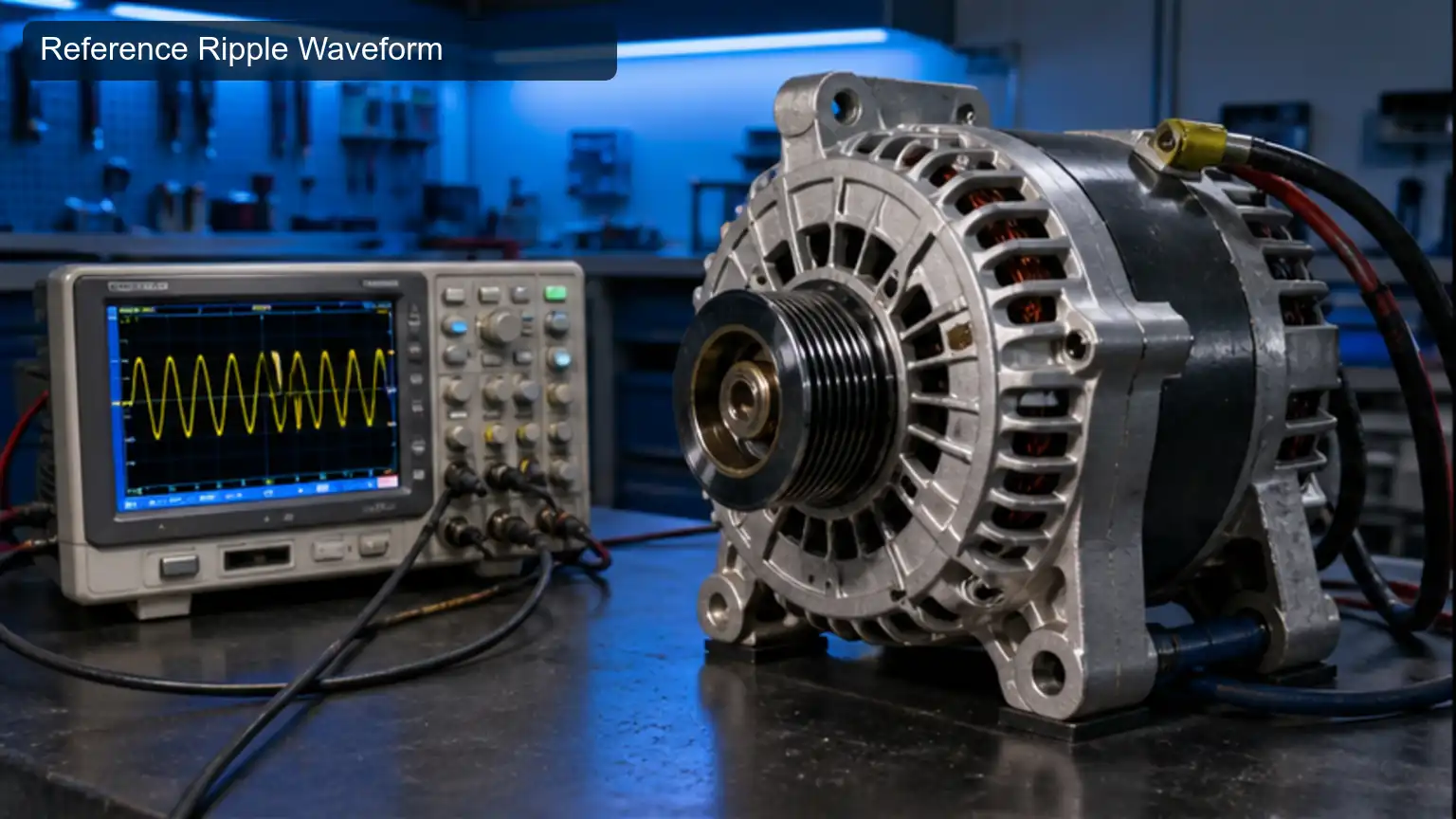
Reference Ripple Waveform documents the article's opening system context with a realistic component or workshop reference.
Apply a safe electrical load, hold specified engine speed, record DC voltage, output current, AC RMS or peak-to-peak ripple, waveform, temperature, and warning states. The purpose here is pattern recognition rather than collection of isolated numbers. The fleet electrician aligns engine speed, load current, ripple amplitude, and waveform image on one timeline so the sequence of the alternator response remains visible.
Interpret engine speed together with load current; either item alone can support several causes. Compare their timing with ripple amplitude, then use waveform image to decide whether the pattern follows electrical demand, pressure, airflow, rotation, temperature, or another case-specific driver.
A strong alternator report saves raw traces or photographs before adding conclusions. The analyst labels normal features, suspected anomalies, and the point where the pattern changes, allowing a supplier to compare claim evidence with the approved sample.
Engine speed: Retain the unedited trace, image, or measured sequence.
Load current: Mark the feature that changes with the complaint.
Ripple amplitude: Compare the same feature under a control condition.
Waveform image: State which cause the combined pattern supports or excludes.
The waveform shape provides information that a single AC number loses. When the pattern is incomplete, collect the missing operating interval instead of repeating the interpretation. The decision gate closes when the evidence sequence explains why the alternator behavior changed.
Release this pattern-analysis stage when the saved pattern and control condition support one interpretation of the alternator evidence. Contradictory traces remain attached as open evidence.
Compare repeating notches, missing peaks, uneven phase spacing, high-frequency noise, intermittent dropouts, and heat-related changes with the alternator's rectifier and winding architecture. This module examines how the alternator behaves after time, heat, load, or contamination has had an opportunity to act. The bench technician defines the exposure interval and tracks notch pattern before, during, and after that interval.
Correlate phase spacing with intermittency rather than treating either value as a universal limit. Add thermal change to show whether cooling, lubrication, sealing, supply, or surrounding hardware changed the result. The exposure must be long enough to reveal the complaint without exceeding the declared duty.
The alternator stress-test worksheet should include ambient condition, starting temperature, applied duty, elapsed time, peak observation, stabilization point, and recovery behavior. These details distinguish a genuine stress-related defect from a test that simply overheated the assembly.
Notch pattern: Establish the pre-exposure reference.
Phase spacing: Capture the peak or worst-case behavior.
Intermittency: Compare the response at a fixed elapsed time.
Thermal change: Document recovery and any permanent change.
A repeatable pattern narrows the fault but still requires supporting tests. A result outside the limit requires the surrounding system to be checked before the alternator is condemned. Approval waits until the stress route and recovery evidence agree.
Approve the alternator stress test after exposure, peak response, stabilization, and recovery form one defensible sequence. The signature covers this stress route rather than unrelated endurance claims.
For a physical reference in the alternator investigation, the alternator product example can help a buyer compare visible interfaces and application clues. Product photography supports this diagnostic stage, but it cannot replace the controlled readings and documented limits required by this section.
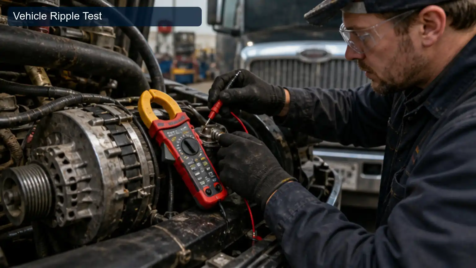
Vehicle Ripple Test documents the article's first diagnostic or inspection module with a realistic component or workshop reference.
Repeat at both ends of the cables, measure loaded voltage drop, isolate approved loads, inspect battery impedance and bank imbalance, and check grounds and remote-sense routing. Bench inspection now tests the internal or component-level theory developed on the machine. The receiving inspector preserves the removed condition, cleans only what the method requires, and records positive drop before disassembly can erase useful evidence.
Quantify ground drop with equipment suited to its expected range, verify battery damping through a second method where practical, and photograph external load beside the part identity. Compensation, temperature, fixture pressure, and zeroing matter when small differences drive the conclusion.
The bench record separates observation from interpretation. It states what was measured directly, what was inferred from the pattern, what limit was used, and whether that limit belongs to the exact alternator case under review.
Positive drop: Preserve the as-removed condition and reference marks.
Ground drop: Record calibrated measurement and environmental correction.
Battery damping: Confirm the suspected mechanism with a second observation.
External load: Connect visible condition with the measured failure path.
Vehicle-side conditions can amplify or mask ripple at the battery. If cleaning, dismantling, or fixture force could have changed the result, the report states that limitation. A batch decision must not rely on a bench value whose method cannot be reproduced.
Accept the alternator bench inspection when the as-removed condition, calibrated values, compensations, and component photographs identify the same mechanism. Any destructive inspection limitation stays visible.
After isolation, inspect rectifier, stator, solder joints, terminals, heat discoloration, bearings, and contamination, then reproduce output and ripple on an approved bench. Competing causes must now be separated so that the replacement addresses the failed section rather than the most visible symptom. The technical buyer compares the evidence for rectifier evidence with the evidence for stator evidence under the same demand before changing any component.
Use thermal damage to test the alternative explanation, then inspect bench waveform for evidence that the host system created or amplified the complaint. Each branch needs a pass/fail reason; swapping parts until the symptom disappears does not identify the original alternator failure.
A cause map for the alternator decision lists the evidence expected if each candidate fault were true. The actual readings are then placed against those expectations, including contradictory observations that prevent premature closure.
Rectifier evidence: Define what this result would mean for the primary theory.
Stator evidence: Compare the alternative component or system response.
Thermal damage: Run the discriminating check that separates both paths.
Bench waveform: Inspect the interface where one fault could imitate another.
Internal evidence should agree with the vehicle waveform before replacement is released. Replace the affected component only after the selected cause explains the complaint and the rejected cause fails its own evidence test. This gate protects the fleet from repeat failure and protects the supplier from an unsupported claim.
Pass the alternator cause-separation stage after the chosen cause explains the complaint and the competing cause fails its defined check. The signature prevents parts substitution from masquerading as diagnosis.
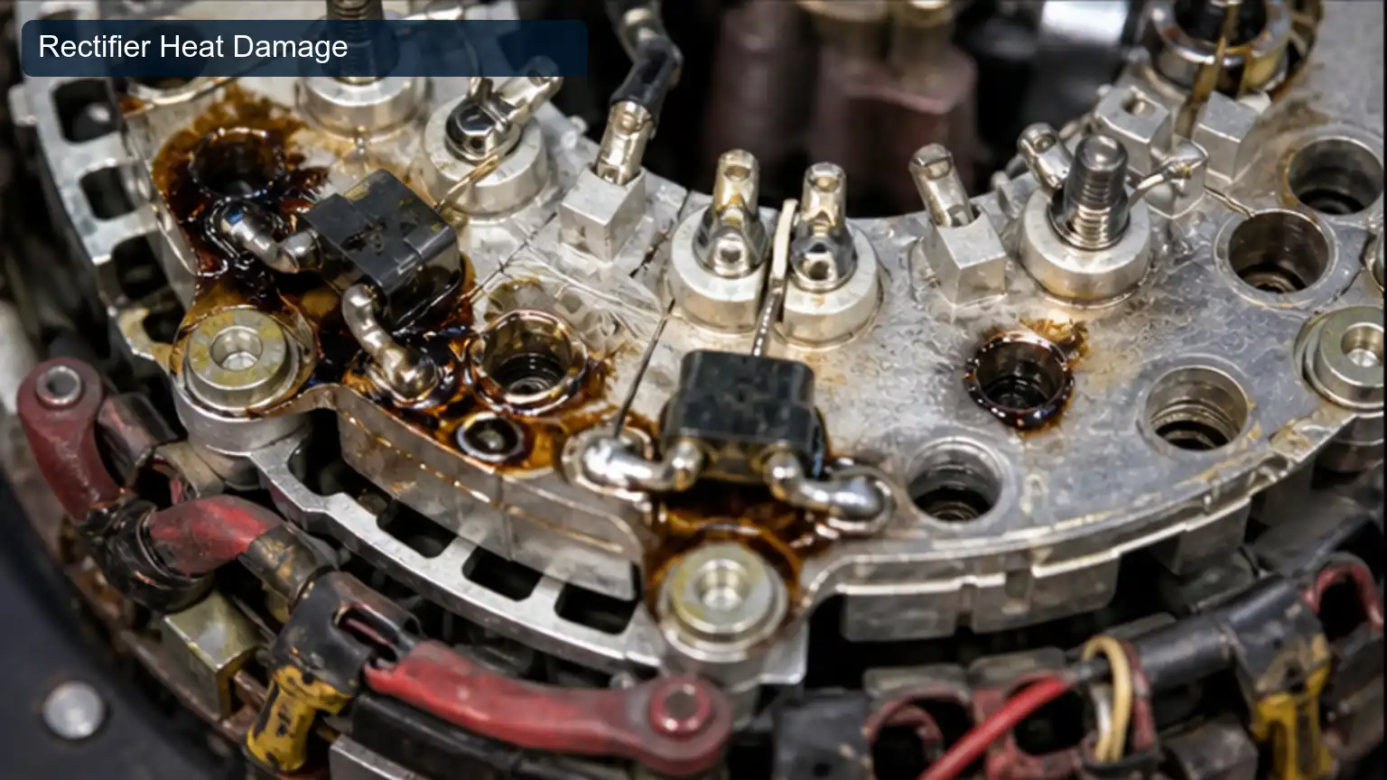
Rectifier Heat Damage documents the article's mid-article evidence module with a realistic component or workshop reference.
Repeat identical speed and load points, compare waveform and ripple, verify remote sense, hot output, temperature, warning behavior, and retained traceability. The final module converts technical findings into an acceptance standard that purchasing, receiving, and warranty teams can apply consistently. The warranty analyst defines how the approved sample and production units will be compared using before-and-after waveform and hot output.
Add sense voltage to expose changes that a label or catalogue cross-reference cannot show. Use serial record to connect each result with the supplier lot, purchase order, and reviewer. Tolerances should reflect the actual heavy-duty operating cycle rather than an unspecified generic test.
The alternator acceptance sheet identifies mandatory evidence, sampling frequency, instruments, pass limits, quarantine action, and escalation owner. It also states which changes require a new sample or field trial.
Before-and-after waveform: Define the release value and sampling method.
Hot output: Compare sample evidence with the incoming lot.
Sense voltage: Retain the technical record that exposes configuration drift.
Serial record: Trace approval, deviation, and claim decisions to one identity.
A controlled comparison proves that the charging fault and not merely the average voltage changed. A production lot advances only when its evidence follows the approved route. Price, urgency, or stock shortage cannot silently waive a mandatory alternator acceptance field.
Authorize alternator production release through a sampling plan, stated limits, traceable lot, quarantine rule, and deviation owner. Production release follows evidence rather than schedule pressure.
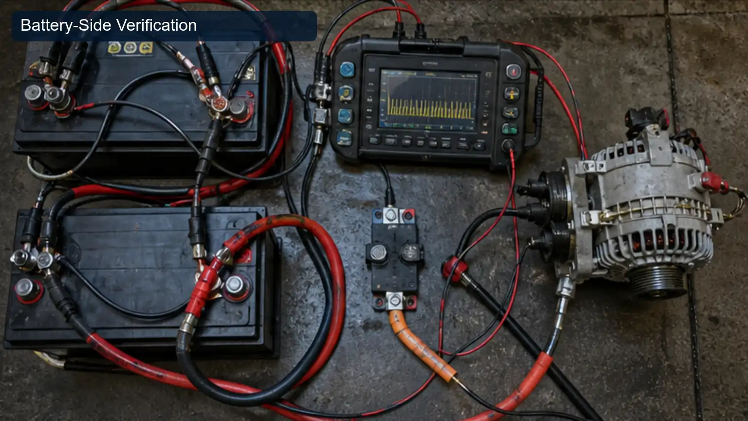
Battery-Side Verification documents the article's final validation or release module with a realistic component or workshop reference.
Identify the alternator, host vehicle or machine, duty cycle, and original complaint for the alternator investigation.
Attach the original alternator ripple measurements, instrument settings, and operating conditions without rewriting the raw results.
Name the person who accepted each alternator limit and the person who owns each open question.
Connect the approved alternator ripple sample with its purchase order, supplier lot, and incoming inspection record.
State whether the requested alternator for the alternator application is new aftermarket, remanufactured, or another declared condition.
List the mandatory interfaces relevant to this alternator case and identify the evidence for each one.
Define sample evidence, receiving checks, packaging, labels, and change notification.
Keep price, MOQ, and lead time separate from unresolved technical fitment.
This alternator workflow works when every reading belongs to a defined condition and every decision belongs to a named owner. The result is a clearer root cause, a more precise aftermarket specification, and a receiving standard that can expose a change before it reaches a heavy-duty fleet.
Keep the AC-coupled waveform, meter bandwidth, loaded output, phase-pattern interpretation, battery and cable checks, rectifier inspection, and repeat hot test. A complete chain prevents normal switching noise or a vehicle-side voltage drop from being reported as a failed alternator diode.
Heavy-duty alternator ripple buyers can review Elecdurauto company information, send the completed evidence through the B2B contact page, and use the Elecdurauto heavy-duty parts catalogue to connect the case with the appropriate product family. The quotation should answer the documented application rather than imply an unverified genuine or OE status.