Your Whole New Supply Chain For Heavy-Duty Parts
Whatsapp:
+86 18915027366
Phone:
+86 18915027366
Views: 0 Author: Site Editor Publish Time: 2026-07-28 Origin: Site
Blower motor resistor faults rarely remove every fan speed in exactly the same way. A truck may lose only the lower stages, operate only on high, work intermittently after a bump, or overheat a connector while the blower still turns. Those patterns are valuable because they point toward different parts of the HVAC electrical path.
This guide turns driver observations into a staged test plan for heavy-duty trucks, buses, and mobile equipment. Buyers can use the Elecdurauto blower motor resistor category to see product formats, while technicians retain the voltage system, connector, speed pattern, motor-current result, and removed-part reference for accurate matching.
The objective is not to replace the cheapest component first. It is to determine whether the resistor or module failed on its own, whether excessive blower current or poor airflow caused the damage, and whether a proposed aftermarket replacement can survive the vehicle duty cycle.
Record every control position, delayed start, intermittent condition, noise, and temperature influence rather than writing only “blower not working.” For blower motor resistor diagnosis, a measured finding gives procurement a stronger basis than appearance, memory, or a broad catalogue description.
Compare key-on engine-off, engine-running, and heat-soaked behaviour so the test captures voltage and vibration effects. During build a fan-speed symptom matrix before removing parts, the technician should identify the test condition, the instrument or visual evidence used, and the point at which the result changes the repair decision. The build a fan-speed symptom matrix before removing parts record stays tied to a repeatable heavy-duty procedure rather than a one-time impression.
The evidence package for build a fan-speed symptom matrix before removing parts should include the application, original markings, all relevant interfaces, observed operating behavior, and any correction completed before retesting. Evidence from build a fan-speed symptom matrix before removing parts helps a remote technical buyer understand why one replacement direction is acceptable and another remains unverified.
Test every fan setting.
Record whether high speed bypasses the resistor.
Note movement-related intermittency.
Capture any stored HVAC faults.
A symptom matrix gives the parts buyer a more useful product request than a generic HVAC resistor name. Before the build a fan-speed symptom matrix before removing parts quotation is approved, assign a clear status—accepted for the named application, pending more evidence, or rejected. The build a fan-speed symptom matrix before removing parts release gate protects the fleet from an urgent substitution and gives the importer a stable specification for repeat supply.
At the end of this build a fan-speed symptom matrix before removing parts module, compare technical fit, operating risk, packaging continuity, lead time, and claim evidence as separate decision factors. Within build a fan-speed symptom matrix before removing parts, a lower unit price does not offset a mismatch that creates a second service visit or an unusable warehouse batch.
Traditional resistor packs drop voltage through staged elements, while electronic modules may use transistor control and feedback. For blower motor resistor diagnosis, that distinction matters when a fleet has repeated downtime and the distributor must separate fitment from system condition.
Identify whether the highest setting uses a bypass relay, whether the switch supplies power or control, and where the ground path joins the blower motor. During map the circuit for resistor stages, relays, and electronic modules, the technician should identify the test condition, the instrument or visual evidence used, and the point at which the result changes the repair decision. The map the circuit for resistor stages, relays, and electronic modules record stays tied to a repeatable heavy-duty procedure rather than a one-time impression.
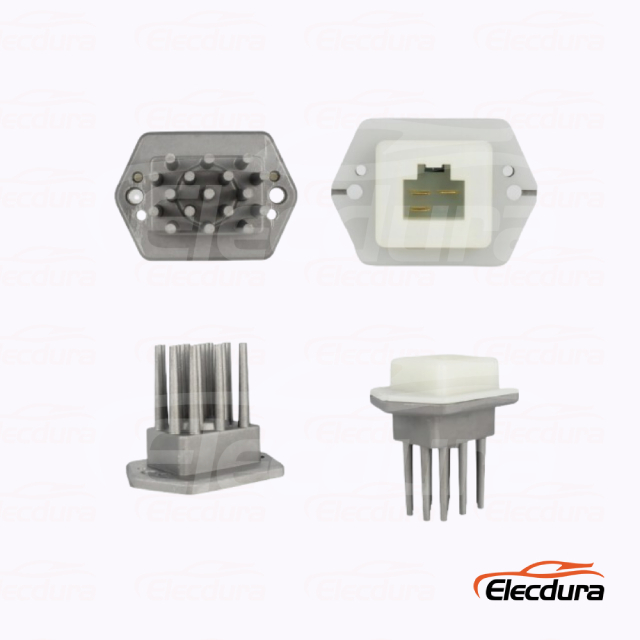
Nissan-reference blower resistor for staged-speed diagnosis.
The evidence package for map the circuit for resistor stages, relays, and electronic modules should include the application, original markings, all relevant interfaces, observed operating behavior, and any correction completed before retesting. Evidence from map the circuit for resistor stages, relays, and electronic modules helps a remote technical buyer understand why one replacement direction is acceptable and another remains unverified.
Use the vehicle wiring diagram.
Identify high-speed bypass logic.
Check the module cooling-air path.
Label connector cavities before testing.
The replacement must match the actual architecture, pin count, voltage, and cooling location rather than a visually similar heat sink. Before the map the circuit for resistor stages, relays, and electronic modules quotation is approved, assign a clear status—accepted for the named application, pending more evidence, or rejected. The map the circuit for resistor stages, relays, and electronic modules release gate protects the fleet from an urgent substitution and gives the importer a stable specification for repeat supply.
At the end of this map the circuit for resistor stages, relays, and electronic modules module, compare technical fit, operating risk, packaging continuity, lead time, and claim evidence as separate decision factors. Within map the circuit for resistor stages, relays, and electronic modules, a lower unit price does not offset a mismatch that creates a second service visit or an unusable warehouse batch.
A worn motor, tight bearing, contaminated wheel, or restricted housing can increase current and overheat the resistor or connector. For blower motor resistor diagnosis, clear acceptance evidence also makes later batch inspection faster because the approved features are already defined.
Measure startup and steady current on the affected speeds, inspect rotation and airflow, and compare voltage drop at the motor and ground. During measure blower current before blaming the resistor, the technician should identify the test condition, the instrument or visual evidence used, and the point at which the result changes the repair decision. The measure blower current before blaming the resistor record stays tied to a repeatable heavy-duty procedure rather than a one-time impression.
The evidence package for measure blower current before blaming the resistor should include the application, original markings, all relevant interfaces, observed operating behavior, and any correction completed before retesting. Evidence from measure blower current before blaming the resistor helps a remote technical buyer understand why one replacement direction is acceptable and another remains unverified.
Inspect wheel contamination.
Check motor noise and free movement.
Measure loaded current.
Verify motor and chassis grounds.
Fleet purchasing should treat an overcurrent result as a motor-system correction, not as evidence that multiple replacement resistors are defective. Before the measure blower current before blaming the resistor quotation is approved, assign a clear status—accepted for the named application, pending more evidence, or rejected. The measure blower current before blaming the resistor release gate protects the fleet from an urgent substitution and gives the importer a stable specification for repeat supply.
At the end of this measure blower current before blaming the resistor module, compare technical fit, operating risk, packaging continuity, lead time, and claim evidence as separate decision factors. Within measure blower current before blaming the resistor, a lower unit price does not offset a mismatch that creates a second service visit or an unusable warehouse batch.
Discoloration, softened plastic, loose terminals, fretting, and arcing show where resistance converted current into heat. For blower motor resistor diagnosis, the workshop should preserve photographs and readings so a warranty discussion does not begin with missing facts.
Inspect both component and harness sides, test terminal tension, and repair damaged wiring before installing a new module. During read connector heat as a failure record, the technician should identify the test condition, the instrument or visual evidence used, and the point at which the result changes the repair decision. The read connector heat as a failure record record stays tied to a repeatable heavy-duty procedure rather than a one-time impression.
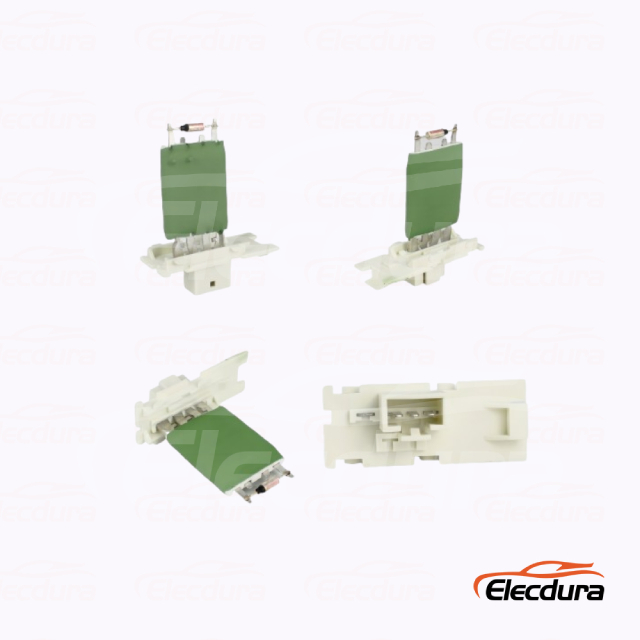
Blower resistor module showing connector and heat-sink form.
The evidence package for read connector heat as a failure record should include the application, original markings, all relevant interfaces, observed operating behavior, and any correction completed before retesting. Evidence from read connector heat as a failure record helps a remote technical buyer understand why one replacement direction is acceptable and another remains unverified.
Photograph terminal colour and shape.
Check crimp and wire condition.
Replace heat-damaged connectors.
Support the harness against vibration.
For distributors, connector photographs help separate wrong-pin fitment from vehicle-side heat damage during a claim review. Before the read connector heat as a failure record quotation is approved, assign a clear status—accepted for the named application, pending more evidence, or rejected. The read connector heat as a failure record release gate protects the fleet from an urgent substitution and gives the importer a stable specification for repeat supply.
At the end of this read connector heat as a failure record module, compare technical fit, operating risk, packaging continuity, lead time, and claim evidence as separate decision factors. Within read connector heat as a failure record, a lower unit price does not offset a mismatch that creates a second service visit or an unusable warehouse batch.
A 24V commercial resistor can resemble a 12V unit while using different values, terminals, and control logic. For blower motor resistor diagnosis, this checkpoint prevents a plausible reference from bypassing the evidence required for a heavy-duty application.
Compare references such as the 2R2959263 24V blower resistor and ME733584 Fuso Canter blower resistor against the removed module, connector, mount, and vehicle application. During match the replacement by voltage, pinout, and mounting airflow, the technician should identify the test condition, the instrument or visual evidence used, and the point at which the result changes the repair decision. The match the replacement by voltage, pinout, and mounting airflow record stays tied to a repeatable heavy-duty procedure rather than a one-time impression.
The evidence package for match the replacement by voltage, pinout, and mounting airflow should include the application, original markings, all relevant interfaces, observed operating behavior, and any correction completed before retesting. Evidence from match the replacement by voltage, pinout, and mounting airflow helps a remote technical buyer understand why one replacement direction is acceptable and another remains unverified.
State 12V or 24V system.
Count and map every terminal.
Confirm mounting plate and screw spacing.
Record vehicle and HVAC application.
The RFQ should include terminal-side photos and the diagnosed fan-speed pattern so the supplier can review fitment responsibly. Before the match the replacement by voltage, pinout, and mounting airflow quotation is approved, assign a clear status—accepted for the named application, pending more evidence, or rejected. The match the replacement by voltage, pinout, and mounting airflow release gate protects the fleet from an urgent substitution and gives the importer a stable specification for repeat supply.
At the end of this match the replacement by voltage, pinout, and mounting airflow module, compare technical fit, operating risk, packaging continuity, lead time, and claim evidence as separate decision factors. Within match the replacement by voltage, pinout, and mounting airflow, a lower unit price does not offset a mismatch that creates a second service visit or an unusable warehouse batch.
A completed repair must restore all intended speeds without excessive current, connector temperature, or intermittent operation. For blower motor resistor diagnosis, the result should be written into the job record before the vehicle, machine, or removed part leaves the workshop.
Operate the blower long enough to heat the module, repeat voltage checks, and verify that the repaired harness remains secure. During approve a repair by repeating the full speed test, the technician should identify the test condition, the instrument or visual evidence used, and the point at which the result changes the repair decision. The approve a repair by repeating the full speed test record stays tied to a repeatable heavy-duty procedure rather than a one-time impression.
24V resistor reference for load-current and terminal checks.
The evidence package for approve a repair by repeating the full speed test should include the application, original markings, all relevant interfaces, observed operating behavior, and any correction completed before retesting. Evidence from approve a repair by repeating the full speed test helps a remote technical buyer understand why one replacement direction is acceptable and another remains unverified.
Run every speed after installation.
Recheck current and voltage drop.
Inspect connector temperature.
Save the accepted part and packaging reference.
This final record allows a repair network to approve the component for repeat stock while retaining evidence for later warranty analysis. Before the approve a repair by repeating the full speed test quotation is approved, assign a clear status—accepted for the named application, pending more evidence, or rejected. The approve a repair by repeating the full speed test release gate protects the fleet from an urgent substitution and gives the importer a stable specification for repeat supply.
At the end of this approve a repair by repeating the full speed test module, compare technical fit, operating risk, packaging continuity, lead time, and claim evidence as separate decision factors. Within approve a repair by repeating the full speed test, a lower unit price does not offset a mismatch that creates a second service visit or an unusable warehouse batch.
A city bus repeatedly loses lower blower speeds, and each failed resistor shows a darkened connector cavity. The fourth diagnosis measures blower current instead of changing the resistor again. A contaminated blower wheel and worn motor bearing raise current well beyond the healthy comparison vehicle, while a loose harness terminal adds local heat. The resistor is the visible casualty, not the complete root cause.
The repair should address the motor, wheel, connector, and airflow path before a verified resistor is fitted. After installation, operate every speed long enough to heat the circuit, compare current with a known-good bus, and inspect terminal temperature. The distributor can then treat the accepted resistor as stock-worthy because the repeated vehicle-side load has been removed and documented.
Blower startup and steady current
Wheel contamination and bearing condition
Harness-side terminal repair
All-speed heat-soak verification
Field Scenario: Three Replacement Resistors Fail on One Bus changes the blower motor resistor diagnosis purchase decision because the failure evidence identifies which conditions must be corrected and which product characteristics must be preserved. The blower motor resistor diagnosis replacement file should contain the measured result, repaired system condition, accepted sample, and a specific rule for future orders.
Fan-speed behaviour is a diagnostic language. When technicians document the missing stages, understand the circuit, measure blower current, and inspect connector heat, they can distinguish a failed resistor from the condition that damaged it. Importers and distributors can then source by verified voltage, pinout, mount, and application instead of appearance alone. Submit those details through Elecdurauto blower resistor support when an OE-reference matching review or wholesale quotation is needed.
A complete blower motor resistor diagnosis inquiry should state the original reference, engine or equipment model, electrical and mechanical interfaces, diagnosed failure mode, required quantity, packaging expectations, and repeat-order forecast. The blower motor resistor diagnosis data set turns speed-stage symptom mapping, motor-current load, and thermal connector evidence into an actionable commercial specification rather than a generic search request.
Original blower motor resistor diagnosis markings and all-side photographs
Vehicle, engine, machine, and operating-duty information
Measured diagnostic results and corrections already completed
Quantity, delivery market, packaging, label, and repeat-order requirements
The blower motor resistor diagnosis procurement data sheet should identify the buyer, destination market, vehicle or machine platform, original references, required quantity, planned reorder frequency, and the technical evidence already collected. A blower motor resistor diagnosis procurement quotation is easier to compare when every supplier answers the same fitment and commercial fields instead of interpreting a short keyword request differently.
For blower motor resistor diagnosis procurement, separate mandatory fitment gates from preferences such as packaging style or delivery timing. The blower motor resistor diagnosis procurement team should mark every unanswered mandatory field as pending, attach photographs at useful angles, and keep the old unit available until the sample is accepted. The blower motor resistor diagnosis procurement written data sheet then becomes the basis for receiving inspection and later investigation of a changed batch.
Readable original markings and reference information for blower motor resistor diagnosis procurement
Vehicle, engine, equipment, operating environment, and diagnosed complaint
Measured electrical, mechanical, thermal, fluid, or airflow checks required by the category
Quantity, destination, packaging, label, lead-time, and repeat-supply expectations
Release the blower motor resistor diagnosis procurement request only when the technical owner and buyer agree on the same application and supply type. For blower motor resistor diagnosis procurement, record whether the proposed item is aftermarket, remanufactured, genuine, or another verified category, and avoid converting an OE reference into an unsupported origin claim.