Your Whole New Supply Chain For Heavy-Duty Parts
Whatsapp:
+86 18915027366
Phone:
+86 18915027366
Views: 0 Author: Site Editor Publish Time: 2026-07-28 Origin: Site
The 24SI name helps buyers find a heavy-duty alternator family, but it does not define a complete charging-system match. Output rating, voltage, mount, pulley, rotation, regulator connection, remote-sense strategy, terminal layout, cooling, and application approval can vary. A catalog match that ignores those interfaces may charge on a bench and disappoint at hot idle on the vehicle.
Elecdurauto supplies a heavy-duty alternator range for commercial trucks, diesel engines, buses, construction equipment, agricultural machinery, and severe-duty aftermarket applications. Product references support OE-number matching and application research. Unless origin is verified, the correct positioning is OE-grade aftermarket replacement or aftermarket equivalent.
This guide treats a 24SI alternator as part of a system. It helps distributors, repair shops, fleet engineers, and importers translate vehicle load, speed, wiring, mounting, and environmental duty into a controlled selection and acceptance plan.
List every continuous and intermittent load. Include engine and transmission controls, lighting, HVAC, cooling fans, aftertreatment, trailer circuits, refrigeration, liftgates, communications, inverters, work equipment, and battery recovery. Record when loads operate together and at what engine speed.
A headline amperage is normally associated with a specified alternator speed and temperature. A truck may spend hours idling with fans, HVAC, lights, and body equipment active. Compare demand with the alternator's hot-idle output, not only with maximum output.
Allow margin for battery recovery, cable loss, high ambient temperature, wear, and future accessories. Excessive oversizing can add cost, belt load, thermal stress, and control complexity, so the margin should be justified by a measured load inventory.
An output curve relates current to alternator shaft speed, voltage, and temperature. Convert engine idle and governed speed into alternator speed using the crank and alternator pulley diameters. Confirm that maximum shaft speed remains within the approved limit.
A smaller alternator pulley can raise idle speed and output, but it also raises bearing, rotor, fan, and belt stress at high engine speed. A larger pulley may protect overspeed while reducing idle reserve. Select the ratio as part of the application, not as a workshop shortcut.
Underhood heat increases winding resistance and challenges the rectifier, regulator, bearings, and insulation. Request output data at relevant temperatures and verify airflow. A cold bench result cannot guarantee hot engine-compartment performance.
Measure pivot or pad arrangement, ear spacing, hole diameters, adjustment points, case envelope, brace locations, and belt-plane offset. Record pulley grooves, profile, diameter, shaft, retention, and fan arrangement. A close visual match can still place the belt out of plane.
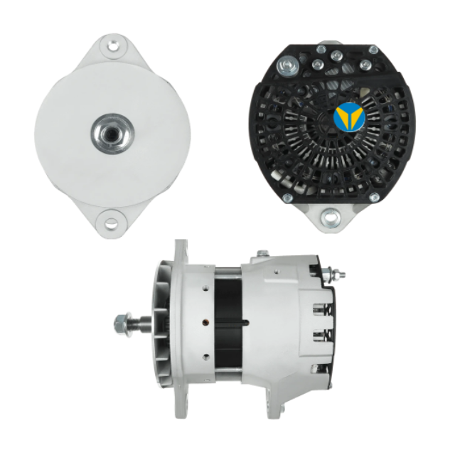
A 40SI 12V 300A-320A J180 alternator example shows a high-output long-hinge architecture. A 24V PAD-mount 40SI-style alternator example uses a different voltage and mounting direction. These examples are not presented as 24SI replacements; they illustrate the interface fields that must be controlled across any family comparison.
Mount, pulley, case, terminals, and cooling must be compared as one fitment package.
Cracks, worn bushings, distorted braces, loose fasteners, and weak tensioners create vibration and belt slip that can damage a new alternator. Correct them before installation and use the specified torque and alignment procedure.
Identify B+, ground, ignition or excite, lamp, remote sense, phase or tachometer, and any communication connection. Use the vehicle diagram and supplier pinout. A physically compatible plug does not prove identical pin functions or regulation strategy.
Remote sensing compensates for voltage loss at a distribution point. Verify where the lead terminates, its protection, and its voltage under load. Moving it to B+ may stabilize one measurement while hiding loss to the batteries or vehicle loads.
If the alternator grounds through its case, clean and secure mounting surfaces and engine-to-battery bonding. If it uses a dedicated ground terminal, match cable size and route. Measure negative-side voltage drop under load instead of relying on continuity.
Use the old label, engine and vehicle information, build date, mount measurements, pulley data, connector photos, and trusted cross-reference. Require at least two independent identifiers. When the vehicle has been modified, physical evidence and electrical measurements take priority.
The A003TV9171A MAN truck alternator demonstrates how an OE reference and vehicle application can narrow a match. Buyers must still confirm voltage, output, mount, pulley, connector, regulator, and environmental duty because one reference may have revisions or market variants.
A Delco Remy, Bosch, Denso, Mitsubishi, or vehicle OE number can identify a target specification. Unless authenticity is verified, describe the unit as an aftermarket replacement for the reference rather than genuine or original.
Alternator life depends on heat, airflow, contamination, vibration, and duty cycle. Record proximity to exhaust and aftertreatment, underhood temperature, airflow direction, oil or coolant leaks, dust, salt, pressure washing, and water exposure. Select protection and cooling for the real environment.
Check fan orientation, inlet and outlet clearance, shields, hoses, and debris. A case that fits physically can recirculate hot air if its cooling arrangement differs. Do not add a shield that blocks airflow while trying to protect the unit from heat.
Oil, coolant, dust, conductive debris, and cleaning chemicals can damage brushes, bearings, insulation, regulator electronics, and terminals. Repair leaks and improve protection before installing the replacement.
For B2B sourcing, request drawings or critical dimensions, output curves, regulation data, ripple limits, insulation results, bearing and rectifier information, sample test records, change control, labels, and traceability. The evidence should connect the approved sample to the production batch.
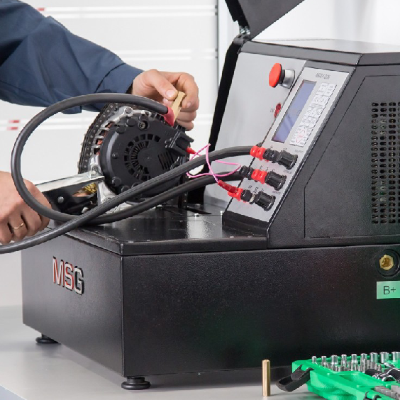
Define test voltage, alternator speed, temperature, load sequence, stabilization time, and acceptance limits. The heavy-duty alternator load-output test method provides a system-oriented framework that can be adapted to sample approval and vehicle commissioning.
Output, regulation, and ripple results are meaningful only when speed, temperature, voltage, and load are documented.
Verify carton and unit labels, voltage, output, mount, pulley, terminals, connector, rotation, finish, fan clearance, and transport damage. Compare a sample with the approved unit and quarantine unapproved changes.
Before starting, confirm polarity, cable support, terminal insulation, belt alignment, battery condition, tool removal, and control connections. Start with limited load and observe warning indicators, voltage, belt behavior, and noise. Stop immediately for smoke, rapid overvoltage, severe belt movement, or hot terminals.
Apply loads in a recorded sequence at idle and an approved higher speed. Measure battery-bank voltage, alternator B+ voltage, current where safe, positive and negative voltage drop, and distribution-point voltage. Repeat after the engine compartment becomes hot.
Measure ripple with the specified instrument and conditions. Abnormal waveform or unstable voltage can indicate a diode, stator, connection, battery, regulator, or control problem. Interpret it with load, speed, and temperature.
Retain the approved reference, application, photos, measurements, output curve, mount and pulley data, connector pinout, test results, packaging, label, and installation record. Assign a customer or fleet fitment code tied to the evidence, not just to a family keyword.
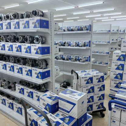
Consistent labels, approved samples, and batch records make repeat alternator orders easier to control.
Record failures by root cause: product, belt drive, cable, battery, heat, contamination, control, installation, or unknown. Compare months, hours, or operating cycles by application group. The data should refine stock, test, and supplier approval rules.
Require reapproval for changes to mount, pulley, regulator, connector, rectifier, windings, bearings, cooling, label, or subcomponent source. A revision may be acceptable, but it should not enter a repeat order unnoticed.
A vehicle may charge correctly at cruise speed and discharge at idle, or show unstable voltage only when accessories switch on. Plot engine speed, alternator speed, load, output current, battery current, voltage, and temperature over the operating event. The pattern separates capacity, drive, control, and connection problems.
Compare the measured demand with the hot-idle point on the output curve. Check pulley ratio, belt slip, regulator command, battery recovery, fan and HVAC operation, and added body loads. A healthy alternator can be undersized for the current duty even when it meets the original vehicle specification.
Investigate cooling, sustained overload, underhood heat, rectifier or stator condition, regulator thermal strategy, belt behavior, and cable resistance. Repeat the test with the same speed and load at documented temperatures. A difference between cold and hot results is useful evidence, not merely variability.
Check battery connection, remote sense, grounds, regulator compatibility, control communication, and load switching. Large inductive or inverter loads can require system-level suppression or control. Do not condemn the alternator until the bus and sensing path are observed during the event.
A strong inquiry reduces back-and-forth and limits catalog assumptions. Send the old-unit label, vehicle and engine data, system voltage, mount and pulley photographs, connector pinout, load inventory, idle and maximum speed, environmental conditions, and measured charging behavior. State the required quantity, packaging, labeling, and acceptance tests.
If the complaint is intermittent, record conditions when the system works and when it fails. Include battery state, ambient temperature, engine temperature, load sequence, warning lamps, and diagnostic codes. Comparative evidence helps separate an application mismatch from a component defect.
The supplier should state any assumptions used to select the alternator, such as mount family, pulley, regulator, remote sense, rotation, or application revision. The buyer can verify those assumptions before sample approval. An unexplained cross-reference should not be the only technical basis.
Transfer the confirmed specifications, drawing points, label, output curve, connector, and test limits into the purchase order and inspection plan. This ensures that production batches are checked against the same evidence that supported the original selection.
An approved sample should have a unique identifier and retained photographs. For production lots, compare critical dimensions, labels, electrical interfaces, pulley, rotation, and a defined performance sample. The release rule should state who reviews deviations and whether the batch remains quarantined while technical clarification is pending.
Supplier bench evidence proves the alternator under controlled conditions; the vehicle test proves the complete installation. Store hot-idle voltage, loaded current, positive and negative voltage drop, ripple, temperature, belt behavior, and diagnostic status with the purchase order. This record provides a baseline if the fleet later adds loads or reports weak charging.
Recheck belt alignment and tensioner behavior, mounting torque where specified, cable support, terminal heat, warning history, and battery condition after the initial operating period. Update the application file if installation access, bracket condition, or control behavior differed from the plan. Early review can catch a system issue before it is classified as an alternator failure.
Keep the review date with the batch record.
Vehicle loads and hot-idle reserve are measured.
Output curve and pulley ratio cover idle and maximum speed.
Voltage, mount, belt plane, rotation, and case clearance match.
B+, ground, excite, lamp, sense, phase, and communication functions are mapped.
Cooling and contamination risks are addressed.
Sample, batch, and vehicle performance evidence is retained.
A 24SI alternator is correctly selected when its output curve, mechanical fit, control strategy, environmental duty, and application evidence agree. Buyers can request 24SI application matching with the old label, truck and engine details, voltage, load profile, mount, pulley, connector photos, quantity, and test requirements. That package supports an accurate aftermarket match without treating a model-family name as a complete specification.