ELECDURA NETWORK

Your Whole New Supply Chain For Heavy-Duty Parts
Whatsapp:
+86 18915027366
Phone:
+86 18915027366
Views: 0 Author: Site Editor Publish Time: 2026-07-29 Origin: Site
Loss of prime after service is often an air-entry problem on the fuel supply side, but bubbles or hard starting do not identify the filter housing by themselves. Verify fuel level and quality, service history, element identity and installation, then inspect every opened seal, drain, sensor, primer, head, connector and nearby hose. Use only the engine maker’s approved priming and low-pressure test procedure; never pressurize or open a common-rail high-pressure system as part of a housing check.
This guide separates observation, isolation and repair release for workshops and parts buyers. It avoids universal pressure and vacuum limits because systems differ.
Record whether the complaint began immediately after filter service, appears only after overnight parking, occurs below a certain tank level, changes with temperature or follows work on a primer, water sensor or drain. Note crank time, visible bubbles where an approved sight method exists, leakage, fuel odor, restriction warnings and any low-pressure supply data.
Pattern | Likely investigation area | Do not assume |
|---|---|---|
Immediate after service | Element seal, center interface, drain, sensor, primer and correct element | The new filter media is defective |
After overnight park | Air entry above fuel level, check valve or seal relaxation | No external wet leak means no air leak |
Only under load | Restriction, collapsing hose, tank pickup and supply capacity | Housing leak is the only cause |
Repeated primer softness | Primer valves, seals, upstream air path and fuel return behavior | The injection pump has failed |
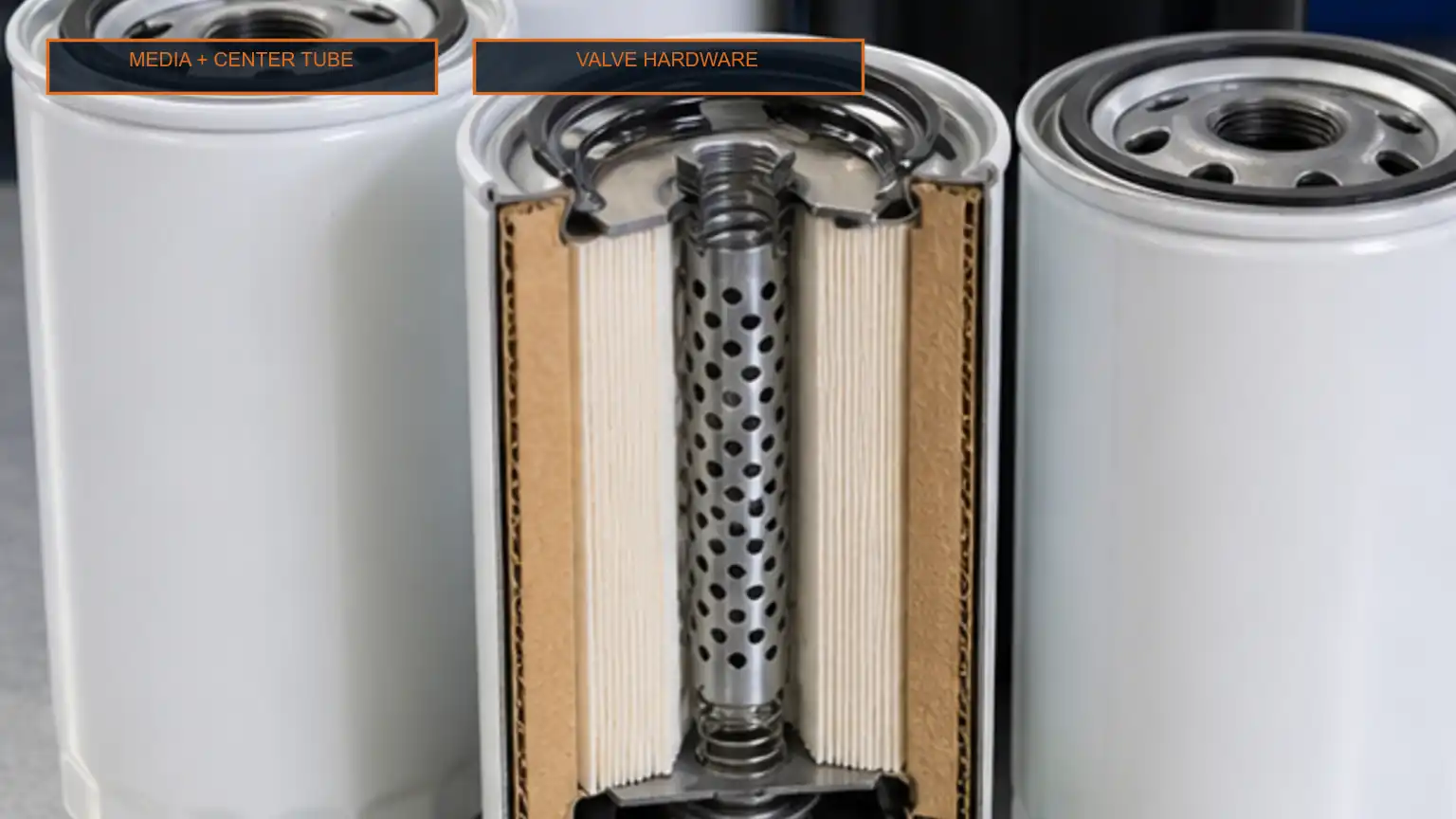
A filter can look similar and still have a different seal or center interface. The staged image provides no interchange authorization.
If the problem began after service, reopen the service record before replacing parts. Confirm the exact element, seal count, seal location, old-seal removal, lubrication method, tightening procedure, drain and sensor transfer and protective-cap removal. A doubled gasket, twisted O-ring, damaged thread or wrong water-sensor seal can admit air without creating a large external leak.
Clean the exterior before opening the system so dirt does not enter. Photograph wetness, dust tracks, loose connectors and hose condition. Mark connections if routing could be confused. Cap openings with clean compatible protection.
Inspect hand-primer movement, cap or plunger seals, check-valve behavior where serviceable, drain hardware, water sensor, heater and thermostatic fittings. Do not use pliers or sealants that the manufacturer does not permit.
Restriction and air entry can coexist. Inspect tank supply, shutoff valves, hoses, quick connectors and pickup condition. A restriction can increase suction and pull air through a marginal seal. Measure restriction or low-side pressure only with the approved connection point and safe equipment.
Test result | Interpretation boundary | Next action |
|---|---|---|
Prime restores operation briefly | Confirms supply-side loss but not the exact joint | Isolate the opened and upstream interfaces |
Bubbles increase with load | May be air entry amplified by suction or aeration from another source | Pair observation with restriction and routing checks |
Restriction high without visible air | Element, hose, pickup or valve may be limiting flow | Identify the restricted section |
No fault after bypassing a suspect assembly under an approved method | Narrows the area but does not identify the component | Inspect and test the assembly off the system if permitted |
The housing, element and service features operate as one assembly. Media alone is not the only possible source of a priming complaint.
Divide the low-pressure path into sections according to the service information. Use approved transparent-line, vacuum, pressure or temporary supply procedures only when they are explicitly permitted and safely contained. Never improvise with compressed air on a fuel tank or open high-pressure injector lines. Record the connection point, condition and result for each step.
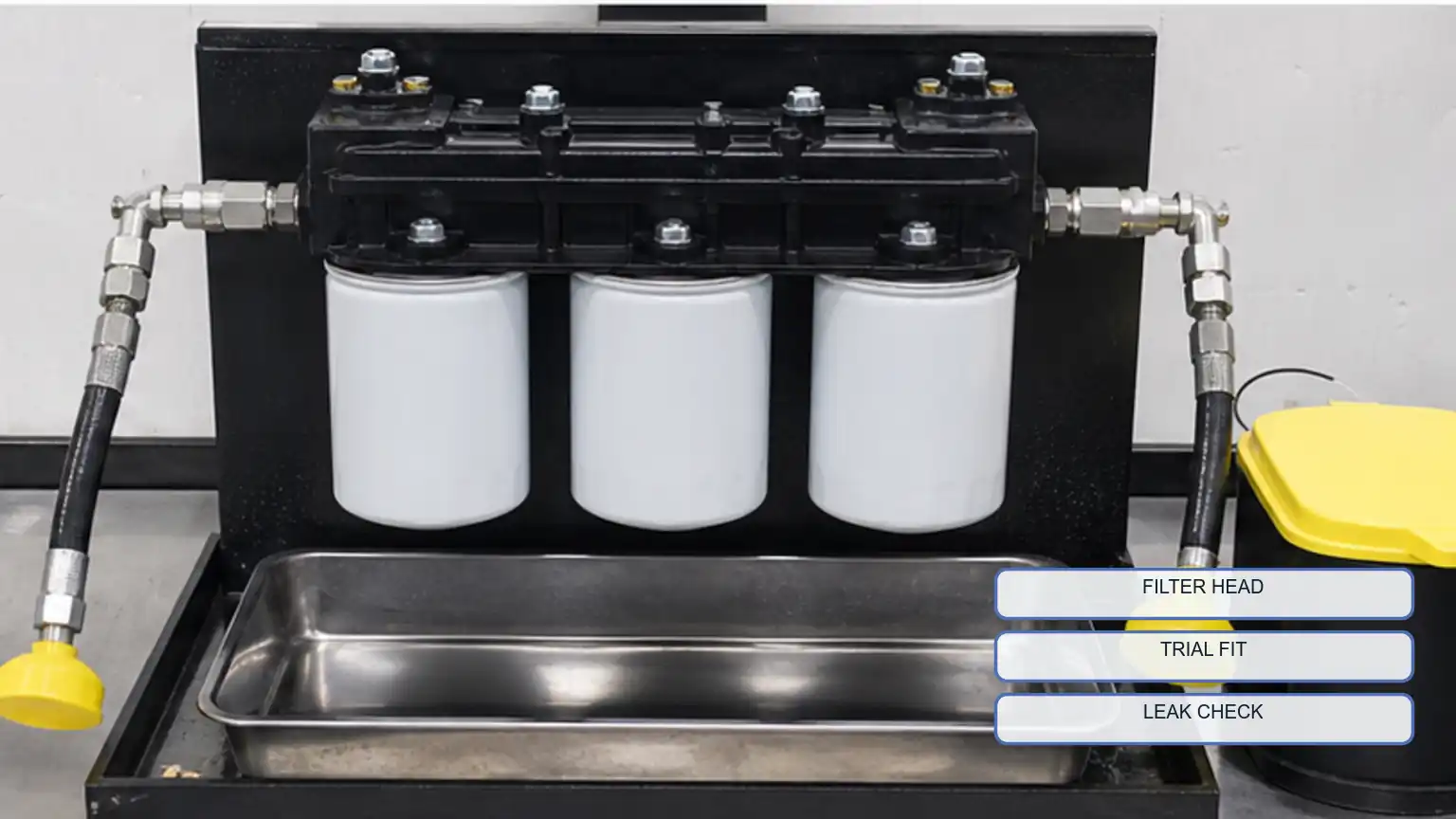
Check sealing grooves, threads, ports, mating faces, casting damage, corrosion, distortion and evidence of overtightening. Confirm that transferred sensors and plugs are the correct design and are not bottoming before the seal is compressed. Replace the housing when the approved inspection finds non-serviceable damage; do not hide cracks or damaged threads with unapproved sealant.
A clean fit and leak check can answer a defined receiving question. It does not prove filtration efficiency or field life.
Install the verified element and seals using the manufacturer’s procedure. Prime with clean compatible fuel and the approved method. Contain spills, inspect for leaks and start the engine only when the system is ready. Monitor low-side supply behavior, bubbles where an approved observation point exists, crank time and response under the original condition. Recheck after a soak period if the complaint occurred overnight.
Engine, equipment and filter-head references
Removed and installed element references and lot codes
Seal, drain, sensor, primer and hose inspection photographs
Restriction or low-pressure test connection, method and result
Repair parts, torque or installation method and post-repair verification
For filter selection, use the primary versus secondary diesel fuel-filter guide and review the fuel filter range. Send the complete assembly identity and service evidence rather than the element color or thread alone.
Yes. A supply-side joint can admit air under suction without producing a large wet leak when the engine is off. Controlled isolation is required.
No. The reference, seals, installation, restriction and interfaces must still be verified. A new but incorrect element can create the complaint.
Only if the exact manufacturer procedure authorizes a controlled low-pressure method. Improvised tank or fuel-system pressurization can be dangerous.