ELECDURA NETWORK

Your Whole New Supply Chain For Heavy-Duty Parts
Whatsapp:
+86 18915027366
Phone:
+86 18915027366
Views: 0 Author: Site Editor Publish Time: 2026-07-24 Origin: Site
A 42MT starter often remains in service long after the original vehicle catalog, fleet numbering system, or supplier record has changed. The starter may be on an older truck, bus, generator, construction machine, agricultural unit, or industrial diesel engine with several repairs behind it. That history makes selection a lifecycle problem, not a simple cross-reference lookup.
Elecdurauto supports heavy-duty aftermarket sourcing through a heavy-duty starter replacement range for trucks, diesel engines, buses, construction equipment, and off-highway applications. OE and brand references are used for compatibility research. An unverified aftermarket unit should not be described as genuine or original merely because it matches a familiar number.
This guide helps fleet engineers, rebuilders, distributors, and importers decide how to support a 42MT application. The process recovers evidence, evaluates the electrical and mechanical system, compares controlled repair and replacement paths, and manages an upgrade without losing the fitment knowledge that keeps legacy equipment operating.
Legacy equipment may carry a rebuilt starter with a remanufacturer tag, an obsolete number, or components from several service events. Gather the complete trail: old labels, housing marks, previous invoices, engine and equipment plates, build dates, electrical diagrams, workshop notes, and photographs. Treat conflicting records as a signal to measure the unit.
Classify each input as direct physical evidence, verified application documentation, trusted cross-reference, or unconfirmed recollection. A direct label and measured mount deserve more weight than a handwritten stock code. Record uncertainty so the buyer knows which points require sample validation.
Do not return, scrap, or disassemble the old starter before the replacement has been checked. The core provides mount, nose, pinion, rotation, clocking, terminal, and clearance evidence that may not exist elsewhere. Photograph it on the engine before removal.
Confirm nominal start voltage, battery configuration, cable length and size, disconnects, grounds, control circuit, engine cranking requirement, and coldest operating temperature. Legacy wiring may contain repairs, added disconnects, or undersized cables that create symptoms attributed to the starter.
During a controlled crank, measure battery-bank voltage, voltage at the starter B+ terminal, case-to-battery-negative drop, and control voltage at the solenoid. The readings show whether the starter is receiving the electrical conditions assumed by the specification.
A vehicle may have moved to a different battery chemistry, capacity, parallel arrangement, or cable route. Document current cold-cranking capability and protection. A replacement decision based only on the original build sheet may ignore decades of electrical changes.
The starter nose, register, mounting pattern, pinion, and travel establish the relationship with the flywheel housing and ring gear. Measure the core and inspect the housing for damage, missing shims, modified holes, or improvised spacers. Any nonstandard feature must be explained before a new unit is installed.
Inspect multiple engine positions because wear often concentrates where the engine stops. Chipped teeth, polished tips, burrs, and uneven impact marks can indicate previous misalignment, incomplete engagement, low voltage, drive wear, or engine kickback. A new starter cannot repair a damaged ring gear.
Look for cracked noses, elongated bolt holes, damaged threads, missing rear supports, and housing contamination. A heavy legacy starter places substantial load on its mounting. Repair the structure and use approved hardware before judging another unit.
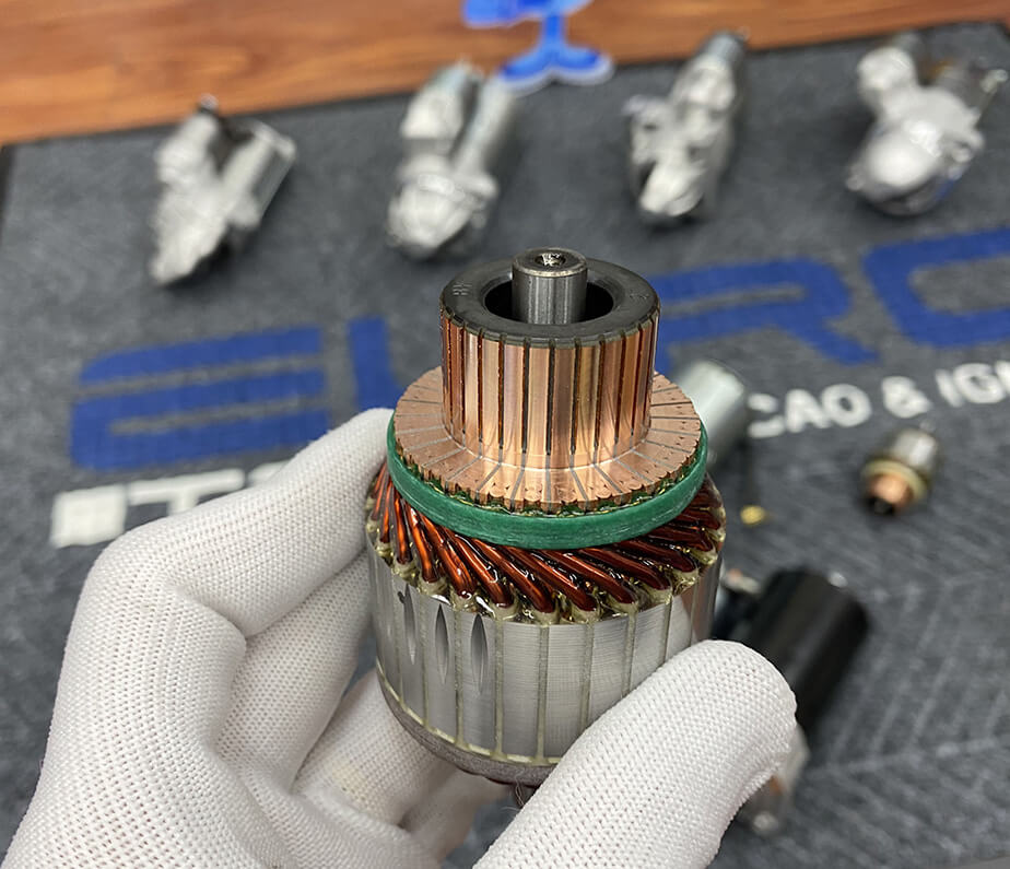
A rebuild decision should begin with core condition and process capability, not nostalgia or parts availability alone. Inspect the armature, commutator, field system, brushes, bearings or bushings, drive, solenoid, housing, insulation, and fastener locations. Reject a core with unsafe structural damage or dimensions outside repair limits.
Internal condition, dimensional limits, and controlled replacement parts determine whether a legacy starter is suitable for rebuilding.
Test armature and field continuity, insulation, commutator condition, solenoid contacts, coil behavior, and voltage drop using approved methods. A cosmetic cleaning does not correct shorted turns, poor insulation, weak magnetic performance, or a high-resistance connection.
Measure shaft, bearing seats, bushings, commutator diameter, drive travel, pinion condition, and housing alignment. Confirm that replacement parts maintain the original geometry and material requirement. A mix of visually similar components can change engagement depth or cranking performance.
Score each path against fitment certainty, component condition, test capability, lead time, downtime, lifecycle expectation, parts availability, warranty, and repeat-order need. The matrix should show why a path is selected and which evidence is still missing.
Repair can be appropriate when the core is structurally sound, critical dimensions remain within limits, qualified components are available, the rebuilder can test loaded performance, and keeping the exact application geometry has high value. Retain before-and-after measurements and test results.
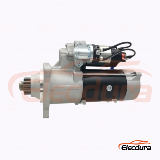
A verified 42MT aftermarket replacement can reduce workshop variability when the application evidence and supplier controls are strong. Confirm voltage, power, rotation, pinion, mount, clocking, terminals, environmental protection, and test limits. Do not accept a family claim without a drawing or approved sample.
A gear-reduction upgrade may reduce weight or improve cranking efficiency, but it must match the electrical, mechanical, and ring-gear interface. The 24V 39MT gear-reduction starter example and 12V 39MT replacement example show that modern alternatives still require voltage-specific and application-specific control.
Create a side-by-side drawing or measurement sheet. Compare mounting flange, register, bolt pattern, nose length, pinion rest and engaged position, tooth geometry, rotation, solenoid clocking, terminal orientation, case envelope, weight, support requirements, and cable routing. Add electrical performance at the expected battery voltage and temperature.
Verify clearance at rest, entry into the ring gear, engaged depth, and release. Use the engine or equipment procedure and suitable gauges. Do not infer correct engagement because the mounting bolts tighten or the engine starts once.
A new starter may draw current differently during pull-in and cranking. Confirm battery capability, cable size, disconnect rating, relay or switch capacity, ground path, and protection. Record voltage drop during a hot and cold start where practical.
A modern gear-reduction starter can be an upgrade candidate only after every electrical and mechanical interface is validated.
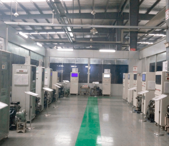
Use one controlled pilot application. Inspect the replacement against the core, install it with documented hardware, and run a defined acceptance plan. Record battery condition, ambient and engine temperature, cranking voltage, voltage drop, speed, current where approved, engagement sound, start time, and release.
Allow the specified recovery time and monitor starter, cable, and terminal temperature. The goal is not abusive cycling; it is to confirm consistent engagement, electrical performance, and release across realistic start conditions.
Controlled endurance evidence supports a fleet rollout better than a single successful cold start.
After an agreed number of starts or operating hours, recheck fasteners, cable support, heat shielding, pinion and ring-gear evidence where accessible, and diagnostic history. A pilot that passes installation but develops abnormal wear should not become the fleet standard.
The final record should be usable by someone who never saw the old unit. Include application identifiers, photos, measurements, electrical diagram, old and approved references, sample serial or batch, supplier drawing, test results, installation notes, exception vehicles, packaging, and reorder criteria.
Create a fleet or distributor reference tied to the complete application file. Do not let the internal code replace the public or supplier reference; it should connect purchasing, inventory, workshop, and warranty evidence.
Require reapproval if the supplier changes the housing, drive, solenoid, winding, connector, subcomponent source, or test process. Also reopen the file when the fleet changes batteries, cables, engine configuration, or operating environment.
Legacy applications need a different stock model from current high-volume trucks. Demand may be intermittent, but a failure can stop equipment for weeks if a core, component, or replacement is unavailable. Classify each 42MT application by criticality, lead time, number of active units, core availability, and approved alternatives.
Retain rebuildable cores for applications with long lead times or uncertain replacement coverage. Tag each core with the vehicle, engine, voltage, reference, condition, and date. Store it dry with protected interfaces. An untagged pile creates inventory cost without providing a reliable service option.
Monitor supplier availability, component discontinuation, fleet retirement plans, and field consumption. A last-time buy should be based on remaining equipment life and validated storage life, not fear alone. Include preservation, rotation, periodic inspection, and the possibility that an approved upgrade will reduce demand.
Review batteries, cables, grounds, heating systems, starter stock, and critical cores before winter or a high-use season. Cold starts and intensive duty expose marginal electrical paths. Planned inspection is less expensive than discovering that a legacy starter and its approved replacement are both unavailable during peak work.
A legacy application file should improve with every service event. Add cranking measurements, temperatures, hours, failure evidence, rebuild findings, ring-gear observations, supplier batch, and replacement outcome. Review the record for repeated patterns instead of treating each failure as isolated.
Age may correlate with insulation, wear, corrosion, or obsolete components, but it is not a diagnosis. Classify verified causes such as brush wear, solenoid contacts, armature fault, housing damage, drive wear, low voltage, contamination, or ring-gear damage. This classification guides stock and maintenance decisions.
Document and remove improvised shims, drilled mounts, undersized cables, bypassed protection, and informal solenoid modifications. If an engineered correction is necessary, issue a controlled drawing and installation instruction. A workaround repeated for years does not become safe merely because it is familiar.
When the last vehicle or machine is retired, update the inventory plan, core holdings, supplier forecast, and internal reference. This prevents obsolete stock from being reordered and lets usable cores or parts be managed deliberately.
A formal closure also protects future technicians from reviving an obsolete workaround when a similar-looking machine enters the workshop. Archive the evidence, mark the approved replacement status, and preserve only the records required for warranty, historical analysis, or a related application.
Review remaining stock, open purchase orders, repair components, and customer commitments at the same time so retirement does not create an unexplained inventory or service obligation.
Legacy demand is often small per application but broad across a distributor's portfolio. Group units by shared physical and electrical specifications, not only by old part numbers. Use minimum stock, repairable-core inventory, supplier lead time, and downtime criticality to set stocking policy.
Reducing many old references to one replacement can simplify inventory, but only after exceptions are tested. Keep a clear exclusion list for voltage, pinion, mount, clocking, or control differences. One failed consolidation can damage a ring gear or strand specialized equipment.
For important low-volume applications, keep an approved sample or a dimensional master with photos and test records. It gives receiving teams a stable reference when labels, catalogs, and suppliers change.
Supporting a 42MT application requires recovering history, measuring the current system, inspecting the ring gear and mount, evaluating core condition, and choosing repair, replacement, or upgrade through documented evidence. The safest path is the one with the strongest fitment and test control, not necessarily the newest or cheapest starter.
Buyers can send a legacy starter evidence package containing label photos, engine and equipment details, system voltage, mount and pinion measurements, cable layout, quantity, and service conditions. That package gives an aftermarket supplier enough information to confirm a controlled replacement or identify where an engineering review is still needed.