ELECDURA NETWORK

Your Whole New Supply Chain For Heavy-Duty Parts
Whatsapp:
+86 18915027366
Phone:
+86 18915027366
Views: 0 Author: Site Editor Publish Time: 2026-07-26 Origin: Site
Alternator overcharging is a charging-system fault that can damage batteries, shorten the life of electronics, create excessive heat, and turn a minor warning into a serious fleet reliability problem. It is tempting to diagnose the fault from one high dashboard-voltage reading, but heavy-duty trucks can use temperature compensation, electronic load management, multiple batteries, and system voltages that make a quick conclusion unsafe. The right response is to verify the measurement, control the risk, and trace the reason the system is charging above its intended range.
For commercial trucks, buses, construction equipment, and fleet workshops, the priority is protection as well as diagnosis. An overcharging system can boil conventional batteries, cause odor or venting, damage sensitive devices, and create a misleading set of symptoms across the vehicle. This guide explains how to test the problem methodically and how to decide whether the alternator, regulator, sensing circuit, wiring, or battery system is responsible. For application-level replacement planning, use Elecdurauto's heavy-duty alternator category as a fitment resource after the root cause is proven.
Overcharging does not always appear as a single obvious failure. A driver may report battery odor, hot batteries, frequent battery replacement, bright or flickering lighting, repeated electronic warnings, or a voltage gauge that appears unusually high after a long run. In a fleet, review whether the complaint occurs on one vehicle or a group of similar units, whether it follows a battery replacement, and whether auxiliary electrical equipment has been added.
Stop and assess the vehicle if batteries are hot, swollen, leaking, venting, or producing a strong sulfur-like smell. Follow site safety procedures and use appropriate protective equipment. Do not assume the issue will self-correct after the engine cools. A battery damaged by overcharge can have reduced capacity even after system voltage appears normal again.
Charging voltage changes with nominal system voltage, battery temperature, battery chemistry, operating mode, and manufacturer strategy. A 24V system should not be judged by 12V values, and a temperature-compensated system may legitimately vary from a simple fixed-voltage expectation. Use the truck or equipment manufacturer's specification and test under documented conditions. The fault is not merely a number; it is a sustained out-of-spec condition with a known measurement method.
High voltage can affect lighting, infotainment, telematics, electronic control units, refrigeration controllers, and aftermarket accessories. Before continuing extended operation, determine whether the voltage is stable and whether any devices show overheating or error codes. Fleet managers should preserve the event data because it can help identify whether the condition appeared after service, an accessory installation, or a battery-system change.
Instrument-cluster voltage displays are useful indicators, but they are not a final diagnostic measurement. Use a calibrated meter at the battery bank and compare it with the alternator output terminal and any relevant sense point. A mismatch between locations can reveal cable resistance, poor connections, or a sensing-circuit problem rather than a regulator failure.
Measure at key stages: engine off, immediately after start, warm idle, elevated engine speed, and with planned electrical loads applied. Record ambient temperature, battery temperature if available, state of charge, active accessories, and system voltage. The trend matters. A reading that rises without control as the engine warms points to a different diagnosis than a brief elevated value during recovery from a low battery state.
If alternator terminal voltage is controlled but battery voltage is abnormal, inspect the positive cable, battery isolator, ground path, and sensing lead. If both are abnormally high, focus on regulation, control, and sensing. If the dashboard differs from a direct meter, investigate the display signal or data-network source before replacing an alternator.
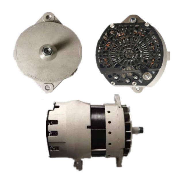
For a high-output application, record the exact alternator configuration before removal. The 55SI 12V 430A J180-mount aftermarket alternator should be matched by system voltage, output, mount, terminals, pulley, and OE or reference number. Output rating alone does not confirm compatibility with the vehicle's regulation strategy.
The regulator controls alternator field behavior, but it only works correctly when it receives valid information and has the right electrical connections. A failed internal regulator, external regulator, sensing wire, poor ground, damaged connector, or control-module issue can lead to excessive charging. The repair must identify which part of that chain is wrong.
Inspect regulator plugs for corrosion, loose locks, backed-out terminals, water entry, heat damage, and broken wires near the connector strain relief. Verify alternator case grounding through the engine and battery negative path. A poor reference ground can cause the regulator to "see" a voltage that does not represent the actual battery condition.
Many charging systems use a sense lead or electronic signal to determine battery voltage. A high-resistance or open sense connection may cause the charging system to react incorrectly. Use the vehicle wiring diagram and measure the sense-point voltage against the battery reference during operation. Do not guess at wire functions by color alone, particularly on equipment that has been repaired or modified.
Modern heavy-duty vehicles may control or monitor charging through an ECU, body controller, battery-management system, or smart alternator protocol. Scan for relevant diagnostic codes, communication faults, and commanded-voltage information when the platform supports it. Replacing an alternator without confirming the control input can leave the overcharge condition unresolved.
A poor battery condition can complicate charging-system measurements. Mixed battery types, mismatched ages, damaged cells, low electrolyte level in serviceable batteries, and incorrect battery-bank configuration can change the way the system responds. An alternator that is asked to recover severely depleted batteries every day may run hot and expose other weaknesses.
Confirm that batteries in series or parallel are compatible in chemistry, capacity, and condition. A mixed bank can create uneven charging and misleading symptoms. Replace batteries according to fleet policy and manufacturer guidance, then verify the charging system again. Avoid evaluating an alternator with a battery bank that is already visibly damaged or unsafe.
Ask about new inverters, work lights, refrigeration equipment, GPS devices, communication systems, battery isolators, or altered grounding straps. An accessory installation can introduce a poor connection, an incorrect sense point, or an unplanned load path. A change that occurred shortly before the complaint deserves as much attention as the alternator itself.
Although belt slip normally produces low output rather than overcharging, a damaged pulley, loose mount, or harness movement can create intermittent behavior that confuses diagnosis. Inspect belt condition, tensioner action, pulley alignment, bracket integrity, and harness clearance. Correcting these factors supports reliable control after the electrical repair is completed.
Once the evidence is collected, choose the repair path that addresses the failed stage. Repair wiring, grounds, sense circuits, battery configuration, or control inputs when they are the cause. Replace or rebuild the alternator only when alternator or regulator testing supports that conclusion. This avoids converting a system fault into a recurring parts claim.
Replace the alternator when internal regulation is proven faulty, output control is out of specification after circuit checks, the unit has heat or contamination damage, or the repair cannot provide dependable traceability. For fleets, a complete application-matched aftermarket unit can be the best way to restore uptime when the old assembly cannot be rebuilt with confidence.
Document the OE number or reference, voltage, amp rating, mounting, pulley, connectors, engine family, vehicle platform, and control arrangement. The A003TV9171A MAN truck alternator is a useful reminder that an OE-reference match must be confirmed against the whole installation, not only a physical outline. An incorrect regulator strategy or terminal design can create a new charging problem.
Describe an unverified non-OE-brand unit as an aftermarket replacement or OE-number-matched alternator. Do not call it genuine or original without proof. Clear positioning helps distributors, fleet buyers, and repair shops compare warranty, packaging, labeling, and repeat-order availability on the facts that matter.
After repair, repeat the voltage test at the battery and alternator terminals across the same operating stages used in the initial diagnosis. Verify battery condition, check for excessive heat, confirm the warning lamp behavior, and scan for any remaining fault codes. Keep the before-and-after log with the vehicle record.
For a fleet program, trend the data. Repeated overcharging complaints on a particular model can expose a harness-routing issue, accessory installation practice, battery maintenance problem, or incorrect replacement application. A disciplined log turns a single repair into useful reliability information for the whole operation.
Alternator overcharging deserves a careful response because its effects extend beyond the charging unit. Correct measurement, safe battery inspection, regulator and sense-circuit checks, and application-accurate replacement matching protect both the vehicle and the procurement process. For B2B technical matching support, send the alternator reference and complete test record through the Elecdurauto contact page.
Overcharging events should be escalated according to the condition of the batteries and vehicle electronics. Where batteries are hot, venting, visibly swollen, or leaking, the vehicle should be isolated and handled under the fleet's battery-safety procedure. Where the system is only showing an abnormal reading without battery damage, the vehicle may still require prompt controlled diagnosis rather than extended operation. The decision should be based on measured risk, not driver convenience.
Capture voltage readings, warning indicators, temperature observations, active electrical loads, fault codes, and recent repair history before disconnecting the battery or alternator. This information can disappear after a reset. It is especially useful when an intermittent high-voltage complaint is reviewed by a central maintenance team or a B2B supplier after the vehicle has left the workshop.
Inspect fuses, fusible links, battery isolators, accessory power modules, and sensitive add-on equipment. A charging-system repair does not automatically prove that downstream devices survived the event. Confirm correct operation of lighting, communication devices, refrigeration controls, and any power-management alarms. This extra check can prevent a second breakdown caused by damage that occurred during the original overcharge condition.
When a fleet records voltage events by vehicle, season, engine family, and alternator reference, it can identify issues that do not show up in individual repairs. For example, a pattern may point to a battery service procedure, a particular harness route, high ambient temperatures, or an accessory retrofit. Trend information should influence spare planning and supplier feedback far more than isolated anecdotal reports.
When overcharging has been traced to an alternator or regulator assembly, the buyer should confirm more than the catalog number. Ask for voltage, amperage, mounting, pulley information, terminal configuration, control or regulator type, OE-reference coverage, packaging consistency, label format, batch availability, and warranty process. This reduces the risk of ordering a physically similar alternator that does not communicate or regulate correctly on the intended truck.
Request clear product images and compare terminal-side and drive-end views with the removed unit. The purpose is not to promise a particular OE brand origin; it is to verify application compatibility. Correct aftermarket positioning, complete fitment data, and a documented diagnostic record create a cleaner purchasing process and help the fleet assess the repair outcome with confidence.
Keep the final voltage readings with the purchase record, particularly where the fleet operates mixed-voltage equipment or has complex auxiliary electrical loads.