ELECDURA NETWORK

Your Whole New Supply Chain For Heavy-Duty Parts
Whatsapp:
+86 18915027366
Phone:
+86 18915027366
Views: 0 Author: Site Editor Publish Time: 2026-09-07 Origin: Site
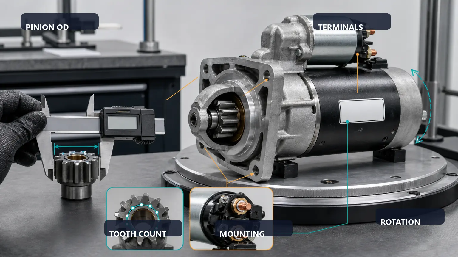
A starter can share the correct electrical rating and pinion data yet still fail at installation because its mounting bolts, nose-housing pilot or flange seat do not match the engine interface. A bolt that bottoms before clamping, insufficient thread engagement, paint or burrs under the flange, a damaged pilot, an unapproved shim or a missing rear support can tilt the starter and alter pinion-to-ring-gear alignment. Before release, compare the exact starter and bolt references, measure the mounting stack, inspect the pilot and seat, confirm full flange contact and use only the approved tightening procedure.
This guide is for heavy-duty starter distributors, fleet workshops and receiving inspectors checking the mechanical mounting interface before installation. The starter, nose-housing pilot, engine seat, bolts, shims and rear support form one alignment system. Matching voltage, teeth and rotation does not prove that the starter axis will sit correctly against the ring gear.
Mounting bolts differ by diameter, thread pitch, under-head length, grip, shoulder, washer arrangement and material specification. Usable thread engagement also depends on the flange thickness, any approved shim or bracket, and the actual depth and condition of the threaded hole. A visually similar bolt can bottom before producing clamp load or engage too little thread to hold the starter under repeated torque reaction.
The nose housing may locate through a pilot diameter, a machined register, a mounting pad or a specified combination. Burrs, corrosion, heavy coating, damage from a loose previous starter or an incorrect housing can prevent square seating. Rear supports and braces can be part of the approved load path rather than optional accessories. Record every interface before the original parts are mixed or discarded.
Complete starter, engine and mounting-hardware references
Bolt diameter, pitch, under-head length, grip and usable thread engagement
Nose-housing pilot diameter, depth, concentricity evidence and damage condition
Mounting-flange thickness, seat flatness, shims, brackets and nearby clearance
Approved tightening sequence, rear-support requirement and installation record
Preserve the installed starter identity and its relationship to the vehicle before cleaning, dismantling or adjustment. Record the operating condition, instrument, datum and procedure behind each observation. That makes the supplier comparison repeatable and prevents an isolated number or photograph from being treated as universal approval.
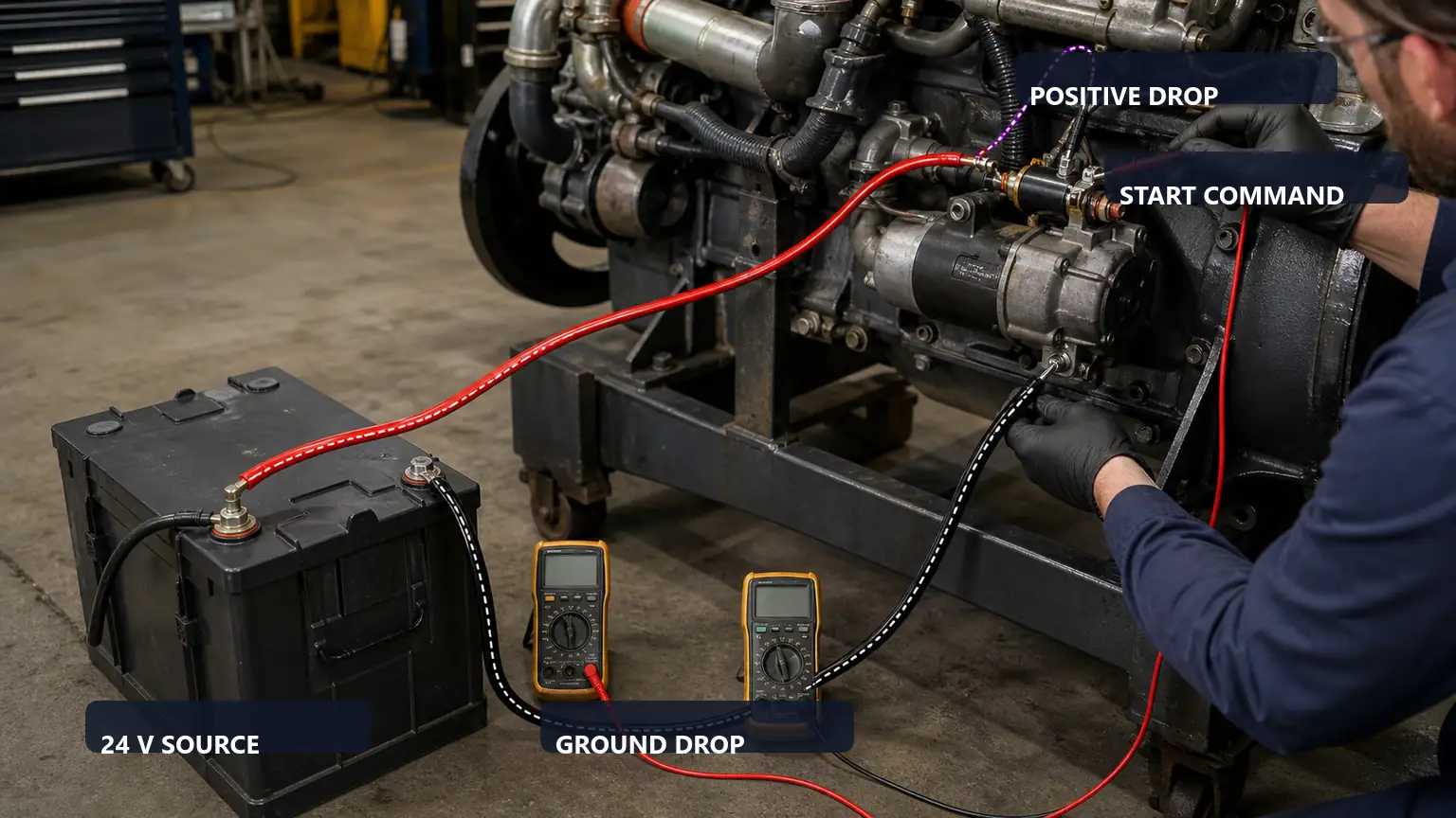
Record the complete installed-unit and system evidence before choosing a starter replacement. The staged image supplies context, not application-specific limits.
Observed evidence | Possible interpretation | Decision-changing check |
|---|---|---|
Bolt tightens before flange seats | Bolt bottoming, debris or wrong mounting stack | Stop and compare usable hole depth with bolt reach |
Starter rocks on the pad | Burr, paint, damaged pilot or distorted flange | Inspect the complete contact and pilot surfaces |
Pinion contact is biased after replacement | Starter axis shifted by mounting mismatch | Verify pilot fit, bracket support and approved alignment method |
Thread damage appears during tightening | Wrong pitch, poor lead-in or inadequate engagement | Quarantine hardware and inspect the engine threads |
Clean the mounting seat and bolt holes only with an approved method. Measure the starter flange, specified shims or brackets and washer stack, then compare the required bolt reach with the usable hole depth. Account for any unthreaded lead, bolt-tip form and clearance; do not assume the full drilled depth is safe thread depth. Verify diameter and pitch with controlled references instead of trying a bolt under force.
Inspect bolt heads, shoulders, threads and washers for stretch, galling, corrosion, impact or previous repair. Inspect the engine threads and the hole entrance. If a bolt stops early, preserve that position and find whether it is bottoming, cross-threading or meeting contamination. Do not add washers or shorten a bolt as an improvised correction unless the approved service information specifies that configuration.
Protect the drive, terminals and open engine interface during inspection.
Never use bolt tightening to pull a mis-seated nose housing into the pilot.
Measure bolt reach against the actual mounting stack and usable hole depth.
Confirm every shim or support bracket is specified for the exact application.
Record final seating, sequence and torque or angle result under the approved procedure.
Use the approved procedure and record the actual condition; appearance by itself is not a pass or fail result for starter mounting bolt nose housing seat inspection.
Support the starter so its weight does not cock the pilot. It should reach the seating surface under controlled hand positioning without using the bolts to draw the flange inward. Inspect the full contact area, pilot engagement, shim placement, terminal and solenoid clearance, drain or vent orientation and the relationship to any rear bracket. Rocking, a persistent gap or witness marks on only one edge requires a hold.
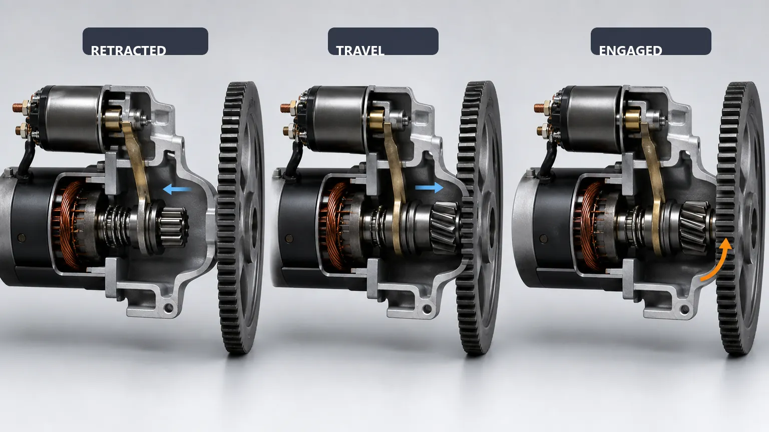
Install the specified hardware and support, then use the approved sequence and tightening values. Record the final seated condition and, where required, verify pinion clearance or engagement by the applicable engine procedure. After the controlled starting test, inspect for movement, abnormal sound, hot terminals and fresh contact evidence. A successful engine start alone does not prove the mounting interface is correct.
Send the same revision-controlled packet to every supplier. Require a complete maker reference, condition, application basis, included hardware, specific starter mounting bolt nose housing seat inspection evidence, traceability, packaging, lead time, warranty and return route. Ask the seller to mark fields it could not verify instead of filling them with a generic direct-replacement claim.
RFQ field | Evidence that can be audited | Reason to hold |
|---|---|---|
Identity | Maker, complete reference, label and proposed condition | Truncated, relabeled or mixed identity |
Application | Vehicle or equipment record plus interface comparison | Visual similarity or unsourced cross-reference |
Functional basis | Named procedure, conditions, actual results and limits | Tested or calibrated without a record |
Commercial scope | Included parts, packaging, warranty and return terms | Condition, core or fulfilment route unclear |
This method does not publish universal bolt lengths, thread-engagement rules, shim thicknesses, pinion clearances or tightening values. It does not authorize drilling, grinding, stacking unapproved washers, omitting a support or forcing a damaged pilot. Obtain the current starter, engine and equipment procedure for exact limits and safety controls.
Approve one identified sample revision before scaling the order. At receipt, reconcile the package, label, starter, report and included parts; inspect protection, contamination, corrosion, impact and mixed-lot risk. Quarantine any mismatch. Installation release must correct the confirmed root cause and reproduce the original operating condition under the applicable service procedure.
Connect the exact sample or production lot to the approved application packet and post-install result.
Use the related Elecdura technical guide and Elecdura product category to organize the evidence before contacting Elecdura. For repeat orders, compare the production lot with the approved sample and require notice before a change to maker, reference, interface, test method, label, packaging or supplied hardware.
No. It may bottom in the hole or enter an unsafe depth before the flange is clamped. Record the applicable identity, procedure and result before changing the purchase or repair decision; the observation alone cannot prove every related interface or system is acceptable.
No. Verify pilot engagement, complete contact and the specified mounting stack. Record the applicable identity, procedure and result before changing the purchase or repair decision; the observation alone cannot prove every related interface or system is acceptable.
Only when the current application procedure explicitly confirms it is not required. Record the applicable identity, procedure and result before changing the purchase or repair decision; the observation alone cannot prove every related interface or system is acceptable.
Measure and record each mounting position. Casting shape, previous repair, contamination or a blind-hole design can change usable depth. Assign bolts only after the approved hardware references and actual mounting stack are reconciled; equal-looking bolts are not evidence that both positions accept the same reach.
No. Preserve the removed unit as a comparison, but verify both references and interfaces. A worn seat, an earlier nonstandard repair or a different nose-housing revision can make an old installation a poor standard. Use it as evidence to investigate, not as permission to copy every feature.
A starter mounting release needs more than electrical and pinion identity. Correct bolt reach, sound threads, an undamaged pilot, full flange contact, approved shims and support, and a recorded tightening result keep the starter axis where the engine design requires it. That controlled interface prevents mounting force from hiding the mismatch that causes the next engagement or housing failure.