ELECDURA NETWORK

Your Whole New Supply Chain For Heavy-Duty Parts
Whatsapp:
+86 18915027366
Phone:
+86 18915027366
Views: 0 Author: Site Editor Publish Time: 2026-08-25 Origin: Site
A heavy-duty starter can be condemned too early when the real restriction is in the battery cable, ground path, or start-command circuit. A voltage-drop test measures the voltage being lost across a loaded section of the circuit, so it shows resistance that a key-off continuity check can miss. For buyers building fleet-service stock, this distinction matters: a correct replacement starter cannot compensate for a corroded cable lug, a loose chassis bond, or a weak command circuit.
Before approving a replacement, compare the fault record with the electrical path and the starter identity. Elecdurauto’s heavy-duty starter motor range is intended for OE-number, engine, voltage, mounting, and drive-end matching; those identifiers should be checked only after the vehicle-side circuit has been assessed under load.
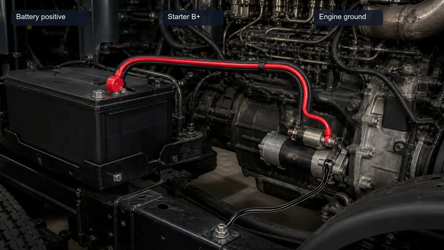
Show the complete battery-to-starter positive and ground return paths that must be tested under cranking load.
A cable can show battery voltage with no load and still fail during cranking. Corrosion inside a crimp, a broken strand beneath insulation, or a loose connection may pass a light continuity test. Once the starter demands current, that resistance consumes voltage and reduces what reaches the solenoid and motor.
A useful audit separates three paths rather than treating the starter as a single black box:
the positive high-current path from battery positive to the starter B+ connection;
the negative return path from the starter housing or engine block back to battery negative; and
the control path that commands the solenoid or integrated magnetic switch.
This separation prevents a familiar purchasing error: replacing a high-torque unit because it cranks slowly when the actual loss occurs at a battery isolator, a frame-to-engine strap, or an auxiliary start relay.
Start with the vehicle manufacturer’s safety procedure. Secure the vehicle, prevent unintended movement, use suitable eye protection, and keep hands, leads, and clothing away from belts and rotating components. A test should begin with batteries that have been charged and individually evaluated according to the battery maker’s instructions. A failed battery can distort every downstream result.
Record the vehicle or machine identity, engine, nominal system voltage, starter reference, complaint, ambient condition, and whether the engine was allowed to start. Photograph the battery posts, starter B+ connection, ground attachment point, and control connector before cleaning anything. That evidence helps a fleet manager decide whether a cable repair, terminal replacement, or starter order is justified.
Place the meter on an appropriate DC range and measure during the same controlled crank event for each circuit section. A peak-capture or hold function can be useful when the event is brief, but it does not replace correct probe placement. Put probes on the actual conductive points being compared, not on painted hardware, loose cable insulation, or a remote junction that changes the section under test.
Voltage-drop limits depend on nominal voltage, cable length, component design, temperature, load, and the engine manufacturer’s procedure. A report should therefore show the measured value, the exact test points, the load condition, and the applicable maker specification. If a workshop uses an internal limit, keep it clearly separate from the vehicle or starter manufacturer’s requirement.
Explain correct probe placement across the positive cable, isolator, and starter B+ terminal.
For the positive-side test, compare battery positive directly with the starter B+ stud while the start event is occurring. The displayed value represents loss across the positive cable, isolators, fuses where fitted, terminals, and their connections between those two points. It is not the starter’s terminal voltage itself.
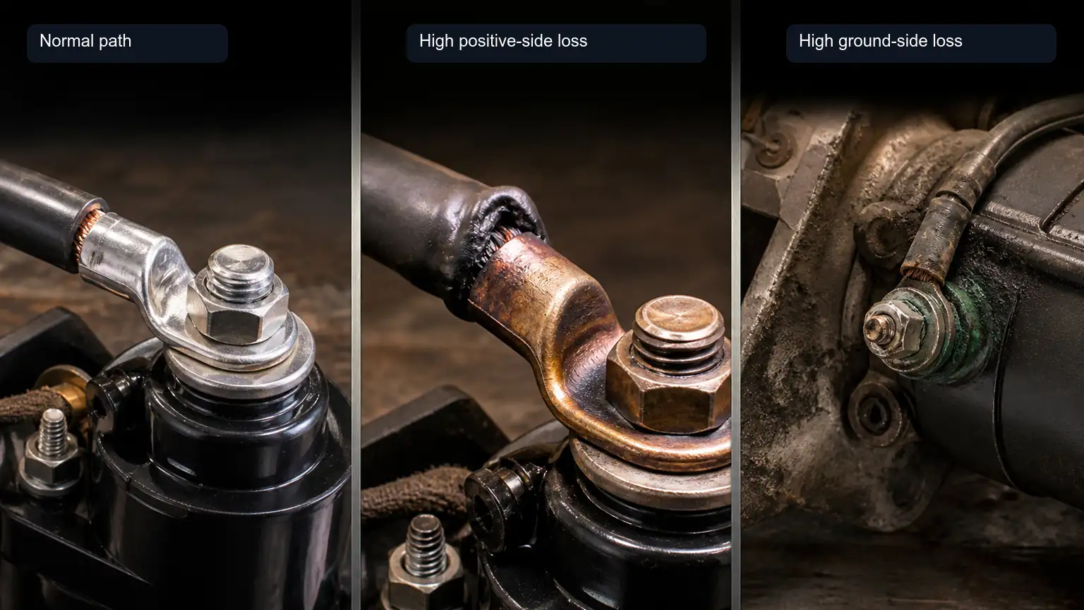
If the positive-side loss is outside the applicable specification, divide the path into smaller sections. For example, compare battery positive to the disconnect output, then across the cable run, then across the final terminal connection. The section that carries the abnormal loss deserves physical inspection. Look for heat discoloration, loosened fasteners, green or white corrosion products, damaged cable routing, incompatible terminal hardware, and signs that a conductor has been overheated.
Do not improve the report by replacing a measured result with a vague statement such as “cable bad.” State the points tested and the repair made. A distributor receiving a warranty return can then distinguish a starter that failed internally from a starter exposed to an external voltage-delivery problem.
The B+ terminal is not only an electrical point. A wrong nut, stacked accessory lead, loose eyelet, or unsupported cable can create heat and intermittent resistance. Compare the terminal layout with the starter drawing and preserve the original routing and strain relief where the vehicle procedure requires it. A visually similar replacement can be wrong if the main terminal, solenoid position, or mounting orientation differs.
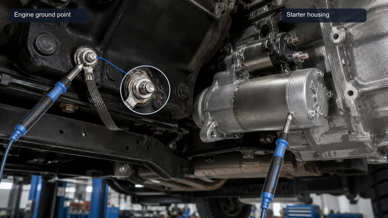
Clarify that ground-side resistance can hide in engine-to-frame bonding and starter mounting interfaces.
The ground side is often missed because the starter housing appears to be bolted directly to the engine. In practice, current may pass through starter mounting faces, engine-to-frame straps, battery-negative leads, chassis bonds, and corrosion-prone joints. A clean-looking ground cable does not prove that each connection carries cranking current correctly.
During the same crank condition, compare a bare-metal point on the starter case or an approved engine-ground point with the battery-negative post. The reading represents the loss across the return path. If it is excessive under the relevant procedure, work backwards through the engine-to-frame bond and battery-negative connections until the loss is isolated.
Removing paint blindly can hide the original cause or create corrosion risk. Instead, identify the intended ground points from the vehicle procedure, inspect their hardware, clean and restore them correctly, and re-test. A heavy-duty machine may have multiple batteries, remote isolators, and auxiliary grounds; the job record should show which path was tested.
A click-no-crank complaint is not the same as a slow-crank complaint. If the motor does not turn, the start command must be evaluated without assuming that the starter motor is at fault. Depending on the design, the command may pass through an ignition switch, neutral or clutch interlock, starter relay, electronic controller, integrated magnetic switch, or a combination of these components.
Use the wiring diagram and the starter manufacturer’s terminal identification. Measure the command circuit at the appropriate S, start, or control terminal during the requested start event. The relevant question is whether the circuit supplies the required command under load, not merely whether a relay clicks. A voltage-drop method can be applied section by section to locate resistance in the control feed or its ground-side command path where the design allows it.
If the high-current paths and command circuit meet the applicable procedure but the starter still fails to operate, the starter and ring gear deserve further inspection. If the command is missing or weak, do not authorize a replacement as the primary repair. This protects the buyer from a repeat no-start complaint and gives the workshop a clearer repair boundary.
For a fleet, distributor, or remanufacturing program, a good voltage-drop record should travel with the quotation request. It should include the engine and chassis or equipment data, old-starter label, nominal voltage, power rating where known, pinion tooth count, rotation, mounting-face photographs, cable findings, and the result of the three-circuit audit.
When the electrical path is proven and a replacement is needed, send Elecdurauto a complete matching package through the heavy-duty parts quotation contact page. A clear technical record lets the supplier verify OE references and physical configuration rather than guessing from a short description such as “24 V truck starter.”
Ask the workshop to retain before-and-after readings, terminal photographs, and the old-unit label. Those records support a more defensible warranty review and help identify patterns in a fleet: repeated positive-side loss may point to a cable-routing or maintenance issue, while a repeated control-circuit problem may point to relay, interlock, or controller logic.
Differentiate normal voltage loss from a high positive-side drop and a high ground-side drop without making the article a generic wiring poster.
Once a whole-path test shows an abnormal loss, divide that same path into sections instead of replacing components one by one. On the positive side, this may mean comparing the voltage across a battery post to clamp connection, a disconnect, a cable run, or the final B+ lug. On the ground side, it may mean comparing across a battery-negative connection, a chassis bond, an engine strap, and the starter mounting interface. Each section should be tested under the same planned crank condition.
A report should not state “positive drop 0.XX V” without identifying the two points. A reading from a battery clamp to a remote junction excludes the rest of the cable, while a reading from the battery post to the starter B+ stud includes it. The end points determine the technical meaning. Use annotated photos or a simple circuit sketch so another technician can reproduce the measurement.
After the safe test sequence, inspect carefully for a connection that has become unusually warm, discoloured insulation, brittle cable covering, or heat marks at a terminal. Heat can support the diagnosis of resistance, but it does not identify the affected section by itself. A temperature observation should remain a supporting note beside the actual voltage-drop measurement.
Do not bypass a fuse, battery isolator, relay, or interlock to make the starter crank. Bypassing a designed protection device may create a safety risk and can erase the very symptom being investigated. If a protection component is suspected, consult the relevant wiring diagram and test it by an approved method.
The first mistake is testing only the positive cable. A heavy-duty starting circuit is a loop, so the ground return requires equal attention. The second is probing on corroded hardware or paint, which introduces a false measurement. The third is using an unloaded reading to clear a cable that only fails when cranking current passes through it.
Another common error is applying a result from one nominal voltage system to another. Battery configuration, cable length, conductor size, ambient conditions, and starter design influence the permitted loss. The report should identify the system rather than copy a threshold from a different truck, machine, or training document.
Finally, do not equate a solenoid click with a healthy control circuit. A relay or solenoid can make a sound while the terminal voltage available under the start command is inadequate for reliable engagement. Treat the control path as a measured circuit, using the exact component documentation.
A disciplined disposition sequence protects both the technician and the buyer. First, confirm battery condition. Second, measure the positive and negative high-current paths under the prescribed load. Third, evaluate the control circuit if the symptom requires it. Fourth, inspect mechanical installation and ring gear condition where indicated. Only then decide whether the starter itself should be removed, returned, or replaced.
For a multi-vehicle fleet, use the same order across repair locations. Standardising the record does not turn every diagnosis into a template; it ensures that every repair starts with evidence that can be compared. The result is a stronger basis for selecting an OE-grade aftermarket replacement and a clearer record if the original complaint returns.
A concise record might read: “24 V construction-equipment starter, slow cranking after hot restart. Battery condition verified under the approved procedure. Positive path measured from battery positive post to starter B+ stud during the defined crank event. Negative path measured from starter case to battery-negative post. Command terminal measured with the specified start command. Abnormal loss isolated across the engine-to-frame strap; strap and fasteners corrected; same endpoints re-tested. Starter label and mounting face retained for matching review.”
This format is useful because it shows what was measured without claiming an unmeasured root cause. It gives a buyer enough context to decide whether the existing starter remains in service, whether a vehicle repair is required, or whether a correctly specified replacement must be quoted.
On systems with multiple batteries, record the battery-bank configuration and the individual battery positions before interpreting a circuit result. A 24 V system may use batteries in series, while other designs use parallel battery connections or an isolated starting bank. A weak connection at an inter-battery link can be hidden if the report mentions only “battery voltage.” Naming the posts and interconnects tested allows the next technician to see whether the loss belongs to a main cable, a crossover link, or a downstream connection.
It is also useful to distinguish a conductor problem from a terminal-interface problem. A cable may be correctly sized and undamaged along most of its length while the crimp, clamp, stud, or washer stack creates resistance at one end. Conversely, a visually clean terminal may conceal broken strands or moisture intrusion inside the cable. Sectional testing creates the evidence needed to choose the correct repair: replace the affected cable assembly, restore the specified connection hardware, or correct the attachment point.
For severe-duty equipment, include operating context in the record. Cold starts, frequent short trips, high vibration, salt exposure, and repeated battery isolation cycles can affect a circuit differently from long-haul highway service. This information does not establish a failure cause on its own, but it helps procurement and maintenance teams decide whether a revised cable route, protective sleeve, service interval, or spare-starter plan is appropriate.
When a starter is returned for technical review, keep the original terminal nuts, auxiliary-lead arrangement, and any non-original adapters with the evidence where safe and permitted. Those small details can explain a voltage-delivery issue that will not be visible after the unit has been cleaned or reconfigured. The review should compare the return evidence with the approved installation layout rather than assuming every external modification was harmless.
Use measurement leads and adapters that are rated and approved for the diagnostic task. A temporary extension lead with an uncertain connection can add its own resistance or create a safety hazard. If access to the designated starter terminal is unsafe or impossible, stop and use the documented alternative test point or service method for that application. A safe, repeatable test is preferable to a more detailed reading obtained from an uncontrolled setup.
Close the ticket only after the stated repair has been re-tested at the original endpoints. That last comparison confirms the correction rather than merely documenting that a connection was disturbed.
A starter voltage-drop test is most useful when it separates battery condition, positive delivery, ground return, and command quality. It does not replace the vehicle manufacturer’s procedure, but it gives a technician and a buyer a structured way to find resistance under real load. That evidence makes the eventual replacement decision more accurate, reduces repeat failures, and protects heavy-duty service inventory from avoidable returns.