ELECDURA NETWORK

Your Whole New Supply Chain For Heavy-Duty Parts
Whatsapp:
+86 18915027366
Phone:
+86 18915027366
Views: 0 Author: Site Editor Publish Time: 2026-07-24 Origin: Site
A slow-cranking heavy-duty truck is often sent straight to the starter-motor replacement queue. That decision can be expensive when the actual restriction sits in a cable, battery terminal, ground path, isolator, or start-control circuit. Voltage drop testing gives fleet technicians and B2B parts buyers a way to measure the available current path rather than infer it from a click, a dashboard warning, or a no-start complaint.
For distributors, importers, and maintenance planners, this matters because a returned starter is rarely only a warranty issue. It consumes labor, creates uncertainty in the next purchase order, and can damage confidence in an otherwise correctly matched product. A disciplined test sequence keeps the diagnosis separate from the sourcing decision, then turns the field evidence into a clearer aftermarket replacement specification.
The process below focuses on commercial trucks, buses, construction equipment, and industrial diesel applications. Buyers who need coverage by OE number, voltage, power, mount, pinion, and application can review the heavy-duty range at Elecdurauto heavy-duty starter motors before requesting a fitment check.
A starter motor can only develop the expected cranking torque when it receives adequate voltage and current under load. A meter reading taken at rest may look healthy while resistance at a damaged lug, undersized cable, loose ground strap, battery disconnect, or corroded junction causes a large loss during cranking. The key question is therefore not whether voltage exists, but how much is lost across each portion of the circuit when the system is asked to work.
This distinction is especially important on heavy-duty diesel engines. Compression, cold oil, accessory drag, long cable runs, high vibration, and frequent stop-start duty all increase the penalty of marginal connections. A vehicle can show intermittent slow crank for weeks, then fail completely on a cold morning or after a long shift. Replacing the starter without recording the circuit losses may leave the next unit exposed to the same condition.
For a purchasing team, a voltage-drop record also creates a practical boundary between a product defect claim and an installation or vehicle-system issue. It can be shared with a repair network, used in supplier discussions, and retained with the return authorization file. That makes repeat orders more predictable than simply classifying every no-start as a starter failure.
Test the batteries and their state of charge before condemning the starter.
Measure the positive and negative cable paths separately under a controlled load.
Record the final total circuit loss, not only the cranking voltage at the battery.
Keep the part number, vehicle application, ambient condition, and test result together.
A starter motor is a load in a wider circuit. A correct replacement decision starts with evidence from that circuit.
The most useful voltage-drop readings come from a repeatable setup. Confirm that the battery bank has been tested, that the terminals are clean and tight, and that the vehicle is safe to crank. Isolate obvious charging-system concerns before the test so a discharged or defective battery does not masquerade as a cable-loss problem. On vehicles with multiple batteries, inspect the interconnects as carefully as the starter cables.
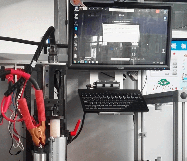
Use a suitable digital voltmeter with clean leads and establish the measurement points before the load is applied. The positive-side test compares the battery positive post with the starter B+ terminal. The negative-side test compares the starter case or ground point with the battery negative post. This approach identifies where voltage is being consumed by resistance instead of being delivered to the starter.
Fleet teams should use the same worksheet across sites. A record that identifies the truck or machine, engine family, electrical-system voltage, ambient condition, battery result, meter points, and measured drops can be reviewed by a central maintenance manager. This produces much better warranty conversations than photographs of a removed unit with no diagnostic context.
Inspect cables for heat damage, frayed strands, rubbing, and green or white corrosion.
Check grounds at the engine block, frame, battery box, and starter mounting surface.
Verify that the correct safety procedure is used for a live electrical system.
Use a load that represents a real cranking demand whenever the test method permits.
Start with the positive path. Place one lead at the battery positive post and the other at the starter B+ connection, then observe the reading while the circuit is loaded or the engine is cranked according to the equipment procedure. A high positive-side loss points the investigation toward the positive cable, disconnects, fuses, terminals, or intermediate connections rather than the starter windings.
Repeat the process on the negative path between the starter case or ground stud and the battery negative post. Heavy-duty grounds are often treated as simple hardware, yet paint, corrosion, loose mounting, damaged straps, and contaminated contact faces can create substantial resistance. A ground-path issue can imitate a weak starter because the motor has no efficient return path for current.
The total is the decision value. Add the positive and negative losses, then compare the result with the vehicle maker or electrical-system guidance. If the total loss is unacceptable, correct the circuit and retest before authorizing a replacement starter. If the total is acceptable but cranking remains weak, the evidence now supports a closer look at the starter, engine condition, control circuit, and battery capacity.
High positive loss: inspect B+ cable gauge, terminals, isolation switches, and connection torque.
High negative loss: inspect battery grounds, frame straps, starter mounting contact, and engine grounds.
Low circuit loss with poor crank: continue to starter-current, battery-capacity, and mechanical-load checks.
Retest after every repair; one corrected connection may reveal another weak point.
The retest verifies the repair and prevents the old reading from being used as a permanent diagnosis.
A starter can receive enough current on the main battery cables yet still fail to engage because the control path is weak. The start-enable circuit may include an ignition switch, relay, neutral or clutch interlock, PTO logic, safety module, solenoid terminal, and multiple connectors. A click/no-crank complaint should therefore not be treated as proof that the main starter motor has failed.
Measure the control voltage during the actual start command and compare the result with the system requirement. If the control input collapses under load, locate the loss upstream before replacing the unit. If the control circuit remains healthy and the main cable losses are acceptable, the evidence becomes more useful for examining solenoid operation, internal contacts, drive engagement, or an electrically damaged starter.
This distinction helps a distributor advise a repair-shop customer without overreaching. The supplier can request the voltage-drop record, vehicle and engine details, mounting photographs, OE reference, and a description of the failure mode. That provides a factual basis for an aftermarket equivalent or OE-reference match rather than a guess based on a generic starter category.
Slow crank commonly points toward available-current, battery, cable, or mechanical-load questions.
Click/no-crank can involve the control circuit, solenoid, or main-current path.
No-click/no-crank may begin with the start command, interlock, relay, or wiring path.
A replacement request should include the observed symptom and test evidence.
Once the circuit is verified, the purchasing conversation can move from diagnosis to fitment. A heavy-duty starter request should combine the OE or reference number with voltage, kilowatt rating, mount pattern, pinion tooth count, rotation, nose housing, connector arrangement, engine platform, and the intended application. Those details reduce the risk of ordering a visually similar unit that cannot survive the duty cycle or install correctly.
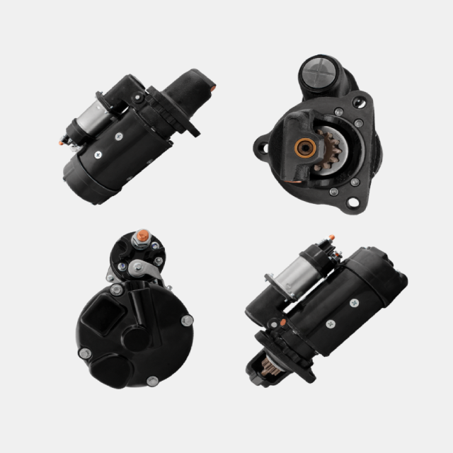
For example, an application requiring a 12V 6kW 37MT-style unit should not be matched only by a brand reference. The buyer should verify the electrical rating, drive configuration, mounting, and engine compatibility. A documented product such as the 12V 6kW 37MT heavy-duty starter motor can be used as a comparison point when the customer is confirming a compatible aftermarket replacement.
Batch planning adds another layer. Importers should ask about repeat availability, neutral or private-label packaging, label consistency, lot traceability, test expectations, and the mix of fast-moving versus application-specific references. These questions belong in the procurement stage because they affect the cost of serving repair networks after the first container or stocking order arrives.
OE/reference number and original label photograph
Vehicle, engine, and duty-cycle description
Voltage, power, mounting, rotation, and drive details
Required quantity, packaging, branding, and repeat-order plan
Voltage drop testing works best when it is not reserved for a breakdown. Fleets can add it to battery service, starter replacement, alternator upgrades, corrosion inspections, and seasonal cold-weather preparation. This creates a small but useful dataset: which routes, climates, battery boxes, connector types, and vehicle families repeatedly develop resistance-related starting problems.
The operating value is not a single number. It is the trend. A maintenance manager can use repeated findings to decide whether cable kits, ground straps, protective covers, terminal treatment, or training should be standardized across a fleet. A distributor can use the same pattern to identify which supporting components should sit beside starter motors in a commercial-service program.
When a customer needs help moving from the record to a replacement plan, Elecdurauto contact support can review OE references, labels, fitment clues, and expected order volume. The goal is accurate aftermarket matching, not an unsupported claim that a component is genuine OE.
Create a baseline after any major battery or cable repair.
Flag recurring vehicles, climates, or cable routes for deeper inspection.
Link repeat failures to a confirmed part and installation record.
Use preventive findings to forecast stocking and service-kit demand.
A useful voltage-drop result has context. Record whether the engine was cold or heat-soaked, whether the battery charger was disconnected, whether the vehicle was parked after a long run, and whether the start attempt was a normal crank or a no-start event. Two readings taken under different conditions can tell very different stories. A workshop that captures the condition, meter connection points, and cranking duration builds evidence that a parts buyer can actually use when deciding whether a starter should be replaced.
Start with the battery posts rather than the cable terminals, then move one meter lead at a time along the positive path. This isolates loss at the terminal, cable, isolator, fuse link, relay stud, and starter terminal. Repeat the same logic on the negative path from starter housing to battery negative. The result is more useful than a single battery-voltage figure because it identifies the component or connection that must be repaired before a new starter is installed. Repeat the sequence after the repair so the work order proves that the loss was removed under the same cranking demand.
Record battery-post voltage during the same crank event.
Label each reading by the two points actually tested.
Repeat an abnormal reading after cleaning or tightening the connection.
Keep the cranking duration consistent enough to compare results.
Remote-battery trucks, buses, vocational vehicles, and equipment with long harness routes often have several joints between the battery and the starter. Each joint may appear acceptable in a visual inspection yet develop resistance under high current. Battery boxes exposed to moisture, frame grounds affected by paint or corrosion, and cable sections routed near heat sources deserve separate measurement. A replacement starter should not be used as a test tool for a path that has not been inspected.
For fleet operations, group repeat slow-crank cases by platform and location. When several vehicles show similar loss at the same frame-ground point, the corrective action may be a maintenance program rather than five separate starter claims. This also helps importers and distributors identify whether a requested starter model is genuinely failing or whether installation conditions are creating a false pattern in the field.
Inspect every isolator, junction, and frame ground in the cranking path.
Check cable routing for abrasion, heat exposure, and unsupported weight.
Compare similar vehicles before classifying multiple parts as defective.
Specify cable and terminal corrections with the replacement work order.
Once the circuit has been corrected or cleared, the replacement specification still needs to be accurate. Match system voltage, rated power, mounting flange, pinion geometry, rotation, terminal layout, solenoid position, and engine application. An OE number or old unit marking can support cross-reference work, but the purchaser should also provide clear photos and application details. This reduces the risk that a physically similar starter is ordered for a different bellhousing or flywheel arrangement.
A concise diagnostic record also improves supplier communication. Instead of a broad request for a heavy-duty starter, the buyer can state that battery condition and cable losses were checked, explain the observed starter behavior, and request aftermarket replacement options against the verified application. That level of information makes technical review faster and gives both sides a more defensible basis for stock planning, warranty handling, and repeat orders.
System voltage and engine or equipment application
Mount, pinion, rotation, and terminal configuration
OE/reference markings and all-side unit photos
Voltage-drop findings and the corrective work completed
A heavy-duty starter motor voltage-drop test is not a paperwork exercise. It identifies resistance that a resting battery reading cannot reveal, separates cable and ground losses from internal starter faults, and gives a fleet or distributor a more defensible replacement decision. Test the main paths, check the start-control circuit when the symptom demands it, correct the losses, and retest before removing a unit.
That sequence protects uptime and protects the parts budget. It also produces the evidence required to match voltage, output, mounting, and OE-reference details to a reliable aftermarket replacement. For buyers managing repeat commercial orders, that evidence is the beginning of a more stable catalog and fewer avoidable returns.
The field record should travel with the purchase request rather than remain only in a technician notebook. It provides the buyer with a clear reason for replacing the unit and provides the supplier with the technical detail needed to identify an appropriate match.
Use the completed record when comparing samples, approving a first batch, or evaluating a repeat-failure claim. It is also a useful reference when a workshop asks whether the fault followed the starter, the wiring, or the vehicle.
Vehicle identification, engine family, and electrical-system voltage
Battery test result and cranking symptom
Positive-side, negative-side, and total voltage-drop readings
Control-circuit reading when applicable
Existing part label, OE/reference number, and mounting photographs
Replacement decision, supplier match, and post-repair retest result