
English
Views: 0 Author: Site Editor Publish Time: 2026-08-19 Origin: Site


A blower that runs on high speed but loses one or more lower speeds is a familiar workshop complaint. It is also an easy place to make an expensive shortcut. The failed thermal fuse or darkened resistor connector may be the first visible damage, yet neither part identifies the heat source by itself. On trucks, buses, agricultural machines, and off-highway equipment, a tired blower motor, weak terminal contact, blocked HVAC airflow, or mismatched control component can make a replacement fail quickly.
Start with the vehicle application and the actual control design, then use the Elecdurauto blower motor resistor category as a reference point for the relevant resistor family. It is useful for comparing visible interfaces and OE-reference applications, but it cannot substitute for the wiring diagram, the vehicle service information, or measured operating conditions. An OE number is an application reference, not a claim that an aftermarket part is OE manufactured.
This diagnostic path treats a thermal-fuse opening as a clue in a heat system. It connects the resistor pack, connector terminals, blower current, cooling air, manual versus PWM architecture, and incoming-part controls. The aim is practical: identify the original cause, repair the circuit rather than merely restoring a speed, and give purchasing or receiving teams a clear basis for a repeat order.
Before unplugging or cleaning anything, record the complaint by speed position and capture the as-found condition. Note whether the blower works on high only, is intermittent on some lower speeds, changes with a bump to the harness, or slows after the cab has warmed up. Photograph the connector face, wire insulation, resistor mount, duct opening, and blower housing. On systems with a burnt plug, the side of the connector that is hottest matters: a feed terminal, ground terminal, or individual speed branch can lead the diagnosis in different directions.
Look at the thermal fuse as a protective device that opened because its local environment became too hot. A clean open fuse with otherwise normal-looking terminals can point toward inadequate cooling through the resistor pack or excessive blower current. Concentrated melting at one cavity, a loose female terminal, or copper discoloration that stops at a crimp points more strongly to contact resistance. Both conditions can coexist. A high-current motor can heat an already marginal terminal until the terminal becomes the hottest part of the circuit.
Do not use the color of a resistor coil or a melted connector as a standalone verdict. Compare the damage with the pack’s airflow direction and mounting position. A manual resistor pack commonly sits in the HVAC air stream so moving air carries heat away from its resistor elements. If the pack was installed outside its designed duct opening, installed with a missing seal, or surrounded by debris, the thermal fuse may have responded exactly as intended. If the resistor body is comparatively clean but one connector cavity is distorted, concentrate on the terminal interface first.
Record the exact speed positions that failed and whether high speed still operates.
Capture the part number, connector keying, cavity count, wire gauge, and any harness repair already present.
Inspect the cabin filter, blower wheel, evaporator face, duct opening, and debris path before removing the pack.
Mark the location of heat damage before cutting back insulation or separating terminals.
The following Volvo-style resistor illustration is a visual reference for mounting and connector comparison; confirm the specific vehicle configuration before using it for fitment.
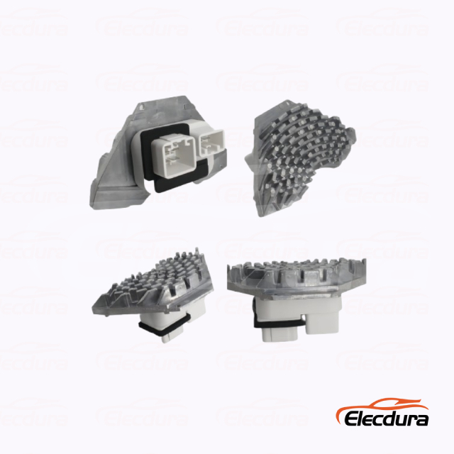
Volvo blower resistor 8693262 for wholesalers 800 800 - Blower Motor Resistor Thermal Fuse and Connector Heat Diagnosis
This distinction changes the entire test plan. A conventional manual HVAC system uses fixed resistor branches to reduce blower speed. The speed switch or relay selects a path, and high speed often bypasses the resistor network so the motor receives battery supply through a separate high-current route. An open thermal fuse or resistor branch therefore commonly removes lower speeds while leaving high speed available. The wiring diagram and connector pinout must prove that arrangement; do not infer it only from the symptom.
A PWM blower module, also called a power stage on many applications, controls motor speed by switching current electronically. It may receive a command signal from the HVAC controller and can have a heat sink rather than exposed resistor coils. High-speed behavior can look similar to a resistor complaint, but meter checks intended for a passive resistor pack can be misleading at a PWM output. The correct diagnosis follows the manufacturer’s service procedure for command, power, ground, output, and thermal control behavior.
Fitting a manual resistor pack where the vehicle needs a PWM module, or selecting a visually similar resistor with a different branch layout, can give wrong fan speeds, overload a circuit path, or leave the original fault unresolved. Match application, system voltage, connector keying, cavity assignment, mounting depth, heat-sink or resistor location, and airflow exposure. Compare the OE reference carefully, but use the exact vehicle and service information to validate the final selection.
The 1696836C1-style component below provides a second physical comparison point. It is not proof that every multi-pin HVAC part shares the same electrical strategy.
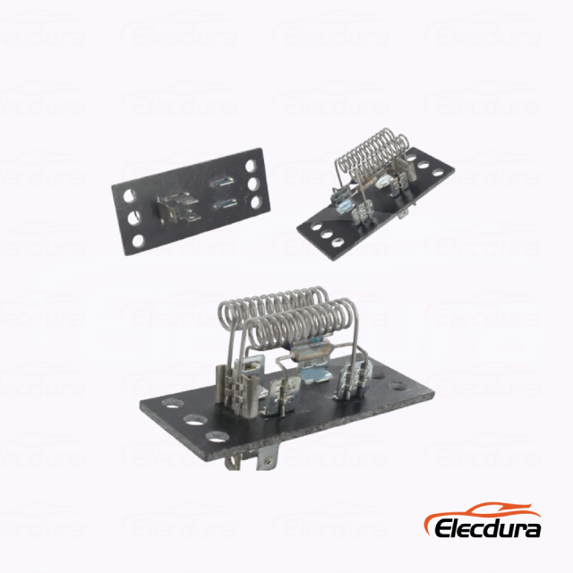
1696836C1 blower motor resistor for wholesalers 800 800 - Blower Motor Resistor Thermal Fuse and Connector Heat Diagnosis
A thermal fuse is not a resettable circuit breaker and should not be bypassed. It is positioned to interrupt the circuit when the resistor assembly reaches a specified thermal condition. Replacing it alone, substituting another protection device, or bridging it for a test defeats an engineered safeguard and can damage the harness, HVAC case, or vehicle. Use the correct component or complete assembly specified for the exact application.
With power removed and the part identified, check whether the thermal fuse is open and inspect each resistor branch according to the correct wiring diagram. Low resistance readings are especially vulnerable to meter-lead resistance, probe pressure, oxidation, and temperature effects. Compensate the leads as required by the meter procedure and compare results only with the correct vehicle or component specification. There is no universal resistance value that proves a blower resistor is good across all applications.
There are two broad ways a thermal fuse can open. The first is heat generated inside the resistor assembly because the motor is drawing more current than the system was designed to carry at reduced speed. The second is heat retained around the assembly because airflow through the resistor pocket is restricted. In service, the parts often tell a blended story: a blower wheel rubbing its housing may raise motor demand, while leaves or a blocked filter reduce cooling exactly when the resistor needs it most.
Test the mechanical side with the blower removed only as far as the service procedure permits. Check for rough bearings, axial play, rubbing, water ingress, and a wheel that is packed with debris. Then inspect the air path with the pack in its intended position. A clean-looking cabin filter does not rule out a blocked evaporator face or debris lodged downstream of the resistor opening. Verify that the replacement pack sits fully in the duct, that its seal is present, and that the air channel was not left covered by insulation or a previous repair.
Open thermal fuse plus normal terminals: investigate motor load, pack seating, and airflow through the resistor cavity.
Open thermal fuse plus a burnt cavity: investigate both the motor and terminal contact because localized connector heat can transfer into the assembly.
Intact fuse with one missing speed: trace the selected branch, switch command, relay path, and connector continuity using the proper circuit diagram.
Multiple erratic speeds on a PWM system: diagnose module power, ground, command, and motor output as a controlled electronic circuit.
The OE 650179-style resistor plate shown here is useful for discussing the relationship between the heat-producing element and its mounting location. Its visible construction is not a universal branch diagram.
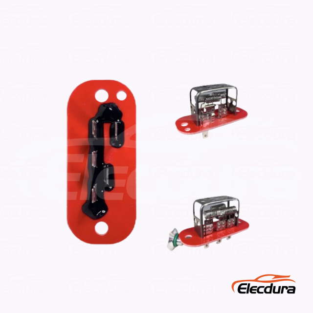
OE 650179 blower resistor plate for wholesalers 800 800 - Blower Motor Resistor Thermal Fuse and Connector Heat Diagnosis
Connector damage is a resistance problem under current, not a visual problem alone. A terminal can look bright at the front yet have weak spring tension, a fatigued crimp, corrosion between mating surfaces, or a partially broken conductor under the insulation. With little or no current, an ohmmeter may report continuity and a static voltage check may look normal. Once the blower pulls current, the same small resistance creates voltage loss and localized heat at the contact.
Perform voltage-drop checks while the blower is operating at the relevant speed and under the condition that produces the complaint. Measure across one connection at a time: across the feed-side terminal pair, the ground-side terminal pair, a suspect splice, or the relevant relay or switch contacts. Do not place one probe at the battery and the other at the resistor and call the result a connector test; that wider reading may hide the location of loss. Repeat after the circuit has reached operating temperature when the service procedure calls for it.
Begin at the supply side, then work toward the motor, recording the voltage drop across each high-current joint at the same blower setting. A joint with a conspicuously higher drop than comparable joints under the specified conditions deserves closer inspection. Follow the return path with the same discipline. If voltage entering the resistor is low because of an upstream feed loss, the resistor may be blamed for a speed complaint it did not cause. If the ground return is poor, heat can appear at a connector far from the actual restriction.
Use a suitable temperature instrument as supporting evidence, not as a replacement for the electrical test. Aim consistently, account for surface finish and access, and compare equivalent points after a similar run time. There is no universal connector temperature or voltage-drop threshold for every truck, bus, tractor, or blower circuit. Use the exact vehicle/service specification and the manufacturer’s repair guidance. Where no approved specification is available, record the results and obtain engineering direction rather than declaring a generic number acceptable.
Replace heat-damaged terminals, housings, seals, and wire sections with an approved repair method for the harness. A new resistor connected to a loose female terminal is not a repair. Remove only enough conductor to reach clean, sound wire; use the specified terminal, crimp tooling, seal, wire size, and splice procedure. Verify terminal retention and mating force after the repair. Avoid twisting wires together, adding an oversized terminal, or packing a damaged cavity with solder, because those methods can alter contact pressure and create a new hot spot.
The power-stage module below helps distinguish the electronic architecture discussed earlier from a passive resistor network. It should be sourced by confirmed application and connector data, not by appearance.
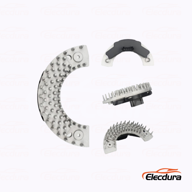
20443826 blower power stage module for distributors 800 800 - Blower Motor Resistor Thermal Fuse and Connector Heat Diagnosis
Current testing belongs in the same work order as airflow inspection. Measure blower motor current with an appropriate clamp meter or the service method at the specified supply voltage and operating speed. Stabilize the test only as long as the manufacturer’s procedure permits. Compare the reading with the correct vehicle specification; motor current varies with system voltage, blower speed, temperature, wheel load, and HVAC restriction, so a generic amperage limit is not reliable.
Listen for bearing noise and rubbing, but do not stop there. A blower can turn quietly while drawing excessive current. Inspect the wheel for debris and deformation, the motor for water tracks, and the housing for evidence of contact. On equipment with staged HVAC operation, repeat the relevant checks at the speed that loads the resistor path. High speed can bypass the resistor on a manual system, so a satisfactory high-speed observation does not clear the reduced-speed circuit.
Resistor elements convert electrical energy into heat by design. The HVAC case routes moving air over or around them to keep that heat within the intended operating range. A plugged intake, collapsed duct, debris-covered evaporator, missing air guide, or resistor installed outside its pocket reduces that cooling. Check the filter and intake path, but also inspect the less visible route from the blower wheel through the resistor location. Use the vehicle service documentation to decide what must be removed and how the air path should be restored.
After correcting a mechanical, airflow, or connector fault, run the system through all available speeds. Confirm that the blower responds correctly, that the repaired connector stays secure, and that loaded voltage-drop readings remain within the applicable specification. Recheck after the circuit has been operating long enough to reveal the original symptom. This is a functional confirmation, not an excuse to ignore a pending code, control-command issue, or unrelated HVAC fault.
For an aftermarket replacement, match the exact application rather than relying on a similar connector or mounting screw pattern. Confirm voltage, HVAC control architecture, connector keying, pin functions, resistor-branch layout or PWM strategy, mounting depth, heat-sink shape, thermal protection arrangement, and intended airflow location. The Fuso Canter blower resistor product page can assist a buyer with application-oriented product research, while the workshop still validates the vehicle’s own service data.
At receiving or pre-installation inspection, compare the incoming part with the removed part and the approved application record. Check label identity, connector cavity count, keying, terminal position, mounting ears, gasket or seal provision, heat sink or resistor-body geometry, and visible workmanship. Inspect for bent terminals, cracked potting, distorted plastic, loose fasteners, shipping damage, or a thermal device that does not match the agreed configuration. A supplier photograph is helpful, but it is not a substitute for checking the part in hand.
Build an incoming check around attributes that affect installation and heat management. Keep an approved reference sample or a complete photographic and dimensional record. When a new lot arrives, compare it against the purchase-order revision and application record before it enters inventory. If the connector, mounting, resistor form, module heat sink, label, or declared reference changes, place the lot on hold for technical review. Do not assume a supersession is valid for every HVAC variant without confirmation.
Verify the ordered application and declared aftermarket/OE-reference number against the purchase order.
Compare connector keying, terminal layout, mounting depth, and air-path interface with the approved reference.
Inspect packaging and labels for part identity, quantity, handling damage, and traceable lot information.
Escalate electrical or construction changes before stock is issued to a workshop.
The 33-31923-style resistor plate below is a useful receiving comparison example. Match the actual order and application record, not only the visual form.
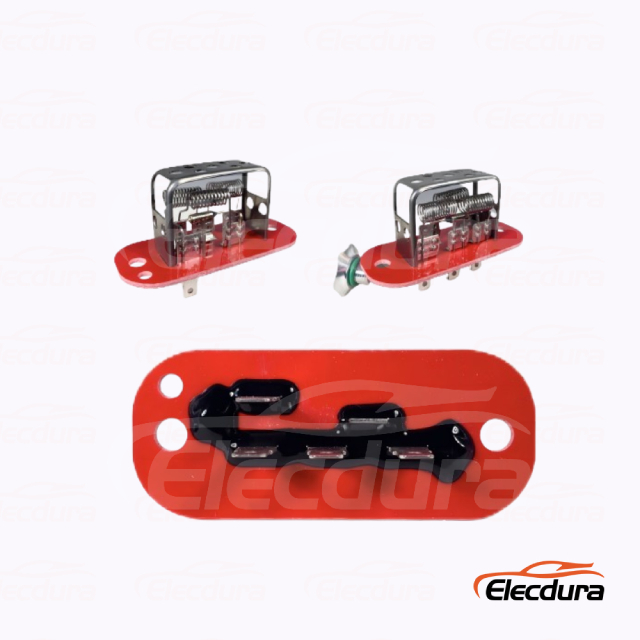
33 31923 blower resistor plate for distributors 800 800 - Blower Motor Resistor Thermal Fuse and Connector Heat Diagnosis
A useful RFQ gives a supplier enough information to quote the right component, not just a part that resembles the failed one. Include vehicle or machine make, model, year or serial range where relevant, HVAC type, system voltage, OE reference, connector photographs, cavity layout, mounting details, required quantity, destination, and expected reorder pattern. State whether the request is for a passive manual resistor pack or a PWM power stage. If the original failure involved connector heat, specify whether a repair pigtail, terminals, seals, or a housing are required as separate items.
Share the relevant findings without turning the RFQ into a claim of universal failure. For example, note that the workshop found a thermal fuse open after restricted airflow, a high motor-current condition, or a heat-damaged terminal, and state which condition has already been corrected. Ask the supplier to confirm the declared application, connector configuration, packaging, markings, lead time, MOQ, warranty terms, and change-notification process. Keep price and availability separate from unresolved technical questions.
A blower resistor thermal fuse opening is a warning that the resistor pack, connector, blower motor, and cooling air path must be considered together. Confirm whether the vehicle uses a manual resistor network or PWM module, test high-current joints under load, repair damaged terminals correctly, and compare all electrical values with the correct vehicle/service specification. That approach helps workshops prevent repeat heat damage and helps distributors receive the intended configuration.
For application discussion or an RFQ, review Elecdurauto company information, then send vehicle details, OE-reference information, connector photos, and quantities through the Elecdurauto contact path. The Elecdurauto heavy-duty parts catalogue can help route the inquiry to the appropriate product family.


