ELECDURA NETWORK

Your Whole New Supply Chain For Heavy-Duty Parts
Whatsapp:
+86 18915027366
Phone:
+86 18915027366
Views: 0 Author: Site Editor Publish Time: 2026-08-21 Origin: Site
Fan-drive complaints rarely arrive as a clean bearing failure. A truck may come in with a growl at idle, a fan that seems locked on after a hot pull, a dark ring around the hub, an intermittent shroud rub, or a belt that throws dust toward the radiator. Any one symptom can lead a technician toward the clutch, but the rotating system includes the fan, hub, pulley, bracket, pilot, belt, controls, and engine-mounted drive. The first job is to identify which part is moving incorrectly and which fluid, if any, has actually escaped.
That distinction matters to a fleet workshop and to a distributor supporting repeat applications. Replacing a clutch without checking its mounting geometry can leave the vibration in place. Replacing a hub because oil is visible can miss a pneumatic line leak that has sprayed road grime across the assembly. A sound inspection records the as-found condition first, measures a known datum second, and only then connects symptoms to the correct service information. For product-family context, see the Elecdurauto fan clutch category.
Never approach a fan drive as though it is passive. Park on level ground, isolate the starting system under the vehicle or engine maker's procedure, prevent automatic fan command, and allow hot components to cool. Confirm that no remote-start, PTO, or thermal control strategy can rotate the fan. Support or remove the fan only as the exact procedure permits. Photograph the leak tracks, belt position, shroud witness marks, and fan-to-hub orientation before cleaning. Those details are often more valuable than a polished assembly after it has been wiped down.
Ask when the noise occurs: cold start, high engine speed, commanded engagement, coast-down, or only after the engine bay is heat soaked. A rumble that follows shaft speed can indicate a hub or pulley bearing, while fan roar tied to coolant temperature or an electronic command can be normal engagement behavior. A cyclic rub may be a blade-tip or shroud-clearance problem, especially when cab mounts, radiator supports, or a fan blade have been disturbed. Document engine speed, coolant condition, ambient temperature, load, and whether the fan was engaged when the concern appeared.
Look for secondary clues without interpreting them too quickly. Red-brown dust at the pulley can come from belt slip; bright fretting at a pilot or flange points to movement at an interface; a narrow polished arc on the shroud can locate the high spot of a fan or support movement. Note missing balance weights, cracked blade roots, bent blades, elongated fastener holes, incorrect spacers, and debris packed between a fan and clutch. A fan blade has a long lever arm, so a small blade deformation can amplify load into a perfectly serviceable hub bearing.
Use a camera and good light before using solvent. Record the highest wet point, the direction of each stain, and whether dirt has adhered to it. Silicone fluid from a thermal viscous clutch, lubricant escaping a bearing seal, compressor or engine oil carried by airflow, and condensed water do not leave the same pattern. If an air-operated clutch is involved, inspect fittings, tubing, rotary unions, and the vent area before a wash can remove bubbles or dye. Mark the fan position relative to the hub so a later runout reading can be correlated with the same blade position.
Cleaning is still useful, but it is a separate stage. Shield electrical connectors, remove loose debris, clean only enough to reveal surfaces, then re-inspect after a controlled rotation or approved pressure test. If the origin becomes less certain after cleaning, report that limitation rather than treating the clean condition as original evidence.
Runout is not a single measurement. The fan blade, clutch flange, hub shaft, and pulley each have different geometry and different causes of movement. Begin with the fan removed or secured as the manufacturer specifies. On a fan mounted to a clutch, compare blade-tip sweep at several blades with the flange and hub readings. A blade-tip variation can be caused by a bent blade, uneven blade pitch, damaged fan pilot, or a loose fan-to-clutch interface; it does not by itself prove that the rotating hub is bent.
Next, inspect the clutch-to-hub connection and the drive pulley independently. A pulley with wobble can load a bearing and create a vibration that appears at the fan. Conversely, a pulley that runs true while the clutch mounting face moves may focus attention on the hub, mounting flange, pilot, or spacer stack. Check the belt for tracking marks and inspect the tensioner and idler path as part of the same diagnosis. Belt tension or misalignment can create radial load and noise without being the original hub defect.
Mount the indicator on a rigid, nonrotating point that is not the surface being questioned. The base must not flex with the bracket or contact the belt. Select a datum from the exact engine or component procedure: commonly a clean machined shaft surface, a specified pilot diameter, or a mounting face. Do not select a rusty pulley lip, painted casting edge, fan blade, or damaged thread merely because it is convenient. Slowly rotate the assembly by hand through a full revolution, watching for a bent contact tip or indicator-base movement.
Radial runout is read with the contact perpendicular to the chosen cylindrical surface. Axial or face runout is read on a specified flat face with the tip arranged parallel to the shaft axis. Record the datum, location, indicator resolution, belt state, fan state, and rotation direction. Repeat after removing dirt or corrosion from the datum if that cleaning does not destroy as-found evidence. A repeatable peak at the same clock position is more informative than a number with no location. If the reading changes when the fan is removed, the fan and its mounting should be investigated before condemning the hub.
The pilot centers the fan or clutch; bolts clamp it. A dirty, corroded, mushroomed, or fretted pilot can force the assembly off-center even when bolt torque is correct. Inspect the pilot diameter, mating bore, spacer faces, and flange for burrs, coating buildup, witness marks, and corrosion pitting. Check for a missing locating ring or incorrect spacer thickness. A distorted flange can produce axial face movement, while pilot damage often creates radial eccentricity. Neither conclusion should be made from a universal number: use the limit and measuring surface published for that exact hub, clutch, and engine arrangement.
Inspect the mounting interfaces and actual application details before comparing a replacement unit.
Hub bearings can feel acceptable with the belt removed and still complain under fan and belt load. Conversely, a slight movement felt by hand may be normal clearance for a particular design. Measure axial and radial movement only where the service literature defines the force, support, and measuring point. If the design requires belt removal or unloading, do it; a tensioned belt can mask movement in one direction and add it in another. Avoid prying against a seal land, thin pulley shell, or fan clutch housing.
For radial play, arrange the indicator on the approved stationary reference and apply a controlled push-pull force at the designated location. For axial play, follow the specified method and avoid using fan blades as a lever. Record whether the fan was installed, whether the belt was loaded, and how force was applied. The meaningful comparison is not between two technicians' hand impressions; it is between the measured condition and the limit for the exact component. If no limit is available, do not invent one from a similar engine family.
Rotate the assembly slowly through several revolutions and feel for notchiness, gravel-like roughness, uneven drag, or a repeatable tight spot. Use a mechanic's stethoscope or approved listening method only with guards and safe access in place; do not chase noise around a running fan. After a controlled operating event, compare temperature at comparable bearing housings using the same instrument and emissivity method. A hot hub may reflect bearing distress, but it can also reflect fan engagement, radiant heat, belt slip, or an adjacent cooling-system condition.
Grease migration is a clue, not a diagnosis. Fresh lubricant behind a seal may be bearing grease; a thin film flung outward could be fluid from another component. Look for blueing, discoloration, metallic debris, damaged seals, and evidence that a failed belt or pulley has side-loaded the bearing. If the hub has been exposed to coolant, pressure washing, dust, or a leaking front cover, contamination may explain shortened life. Record the environmental exposure because it changes both root-cause analysis and an RFQ for a replacement assembly.
Make a hot/cold comparison when it is safe and relevant. Note cold rotational feel, then compare it after the operating conditions that produced the complaint. A bearing that becomes noisy only when heat expands the assembly needs different scrutiny from one that is rough from the first turn. Let the engine and fan drive cool before repeating a hands-on measurement. The purpose is to observe change, not to create a hot-running hazard.
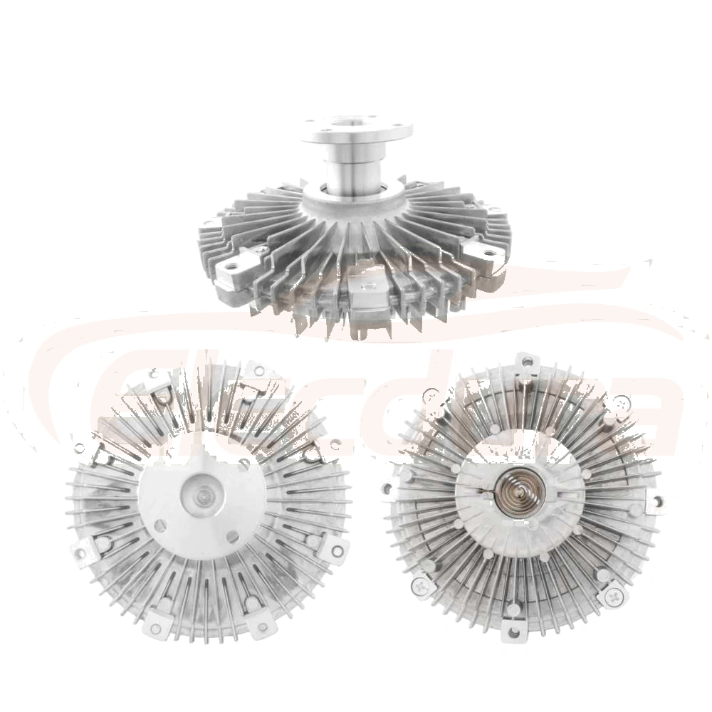
A visual product reference cannot replace play, runout, and bearing-condition measurements on the installed drive.
Seal-leakage inspection begins by naming the medium. A viscous clutch may show silicone-fluid leakage around its sealed working chamber. An air-operated clutch can lose control pressure at tubing, fittings, a rotary air path, actuator seals, or the clutch body. A hub bearing seal may release grease, while engine oil or coolant can be blown across the same area from an unrelated source. Airflow, pulley rotation, and fan wash can carry fluid a surprising distance, so the lowest wet point is not automatically the origin.
Trace upward and inward from the deposit. Inspect behind the pulley, around the shaft, at the bearing-seal interface, and at any pneumatic connection. Check whether the residue is fresh, dry, tacky, oily, or mixed with belt dust. On a pneumatic unit, use the exact test pressure, isolation method, and leak-detection approach stated by the manufacturer. A pressure drop without external bubbles can indicate test-fixture leakage, an internal leak, or a control-circuit issue. Verify the test equipment before opening the clutch.
An air leak changes engagement behavior; a bearing-seal leak changes lubrication retention and can contaminate adjacent parts. They may coexist, but the repair path is not interchangeable. Do not apply air pressure to a clutch beyond its published procedure, and do not assume a compressor hiss identifies the clutch itself. Isolate the supply line, fittings, valve, and actuator circuit in sequence. Document pressure, dwell time, ambient conditions, and the exact connection used. On electronically controlled units, inspect harness routing, connector seals, command status, and feedback before calling a no-engagement complaint mechanical.
Lubricant migration deserves a second look after the source is cleaned and the system is exercised safely. A bearing seal can sling lubricant in a radial pattern; leakage from above may follow gravity before airflow redirects it. Dust accumulation at the rear of a pulley may indicate a long-running seep, while a sudden wet spray may follow a seal rupture or a failed nearby line. If disassembly is required, preserve photographs of the seal lips, race surfaces, and contamination. The exact failure mode supports a better warranty decision and a more useful supplier discussion.
Leak medium, engagement type, and mounting geometry must all match the actual fan-drive design.
A thermal viscous clutch, a pneumatic clutch, and an electronically commanded clutch do not share the same expected cold drag or engagement test. Identify the control type from the unit and vehicle documentation before turning the fan by hand. A viscous clutch may have noticeable resistance when cold; that observation alone does not establish a fault. A pneumatic or electronic unit may remain disengaged until a command is present, while its hub bearing still rotates continuously with the drive.
For a pneumatic system, confirm supply quality, line routing, valve function, and the clutch's commanded state. For an electronic system, use the appropriate diagnostic information to verify request, power, ground, communication where applicable, and feedback. For a thermal unit, follow the published temperature and test procedure. Keep engagement findings separate from hub runout and bearing findings. A clutch can engage exactly as commanded while a damaged bearing makes the fan unsafe; a quiet hub can coexist with a control fault that leaves the fan engaged too long.
When testing under operating load, verify belt alignment, belt condition, tensioner travel, pulley grooves, and fan clearance first. Fan load rises sharply with speed, and an incorrect fan, altered pitch, damaged shroud, or excess restriction can change the load the hub sees. Compare before-and-after observations at similar coolant temperature, engine speed, and ambient conditions. This avoids attributing a change in fan sound to the clutch when the real difference was operating demand.
There is no responsible universal runout, end-play, pressure-decay, temperature, or fan-speed tolerance for all heavy-duty fan drives. Limits depend on the engine front-end arrangement, hub design, bearing type, fan diameter, clutch technology, pulley system, and the location being measured. Source the service limit from the exact engine manufacturer, vehicle manufacturer, clutch maker, or hub maker using the component number and application. Record the document title, revision, measurement point, units, and test condition alongside the result.
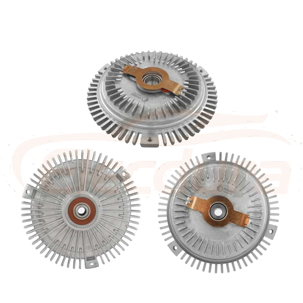
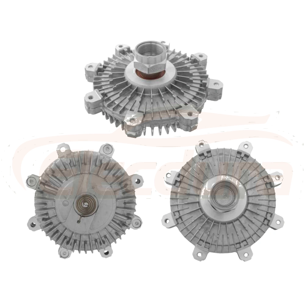
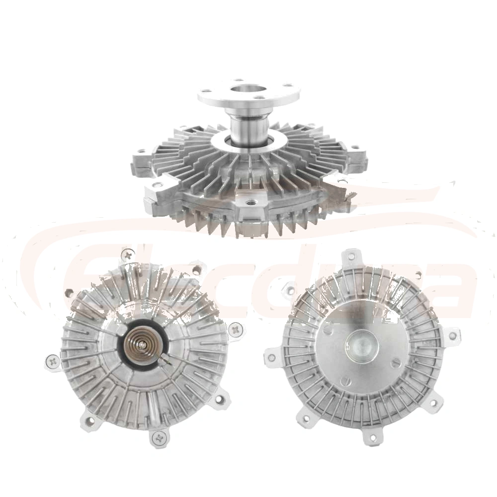
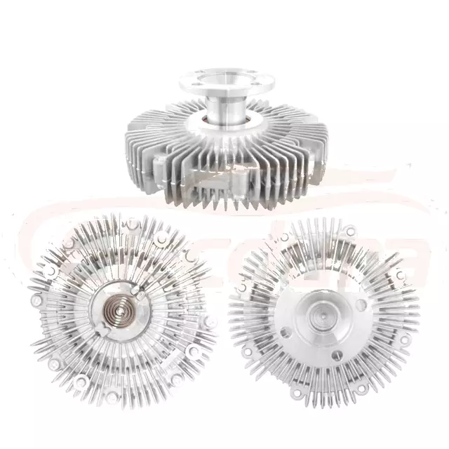
If a published specification is absent, request it rather than transferring a value from a look-alike part. A distributor can state that an item has been inspected to its declared manufacturer procedure, but should not claim fitment or performance based solely on visual similarity. The fan clutch item example is useful for product-reference comparison, while the OE or manufacturer record remains the authority for the installed system.
Match the replacement by OE reference and by physical interfaces. Confirm clutch type, fan rotation, pilot diameter, bolt circle, flange offset, pulley count and profile, shaft arrangement, mounting depth, fan bolt pattern, connector or air-port configuration, and any thermal or electronic control feature. Verify the engine, chassis, and production break where the catalog requires them. Never substitute a part because the outside diameter looks close or because the fan bolts happen to align.
On arrival, inspect the unit before installation. Check markings and OE-reference cross-references, packing protection, connector seals, air fittings, thread condition, pulley finish, pilot condition, flange faces, and evidence of transport impact. Rotate it only as its design allows; compare its visible geometry with the approved application record. For a batch purchase, sample each delivery according to the buyer's plan and retain photos of identifiers and critical interfaces. A changed casting, fitting, connector, or offset warrants technical review before stock is mixed.
An RFQ should include the OE reference, engine model, vehicle or equipment application, VIN range or serial break when relevant, control type, fan diameter and mounting pattern, pilot and bolt dimensions, pulley description, measured offset, rotation direction, connector or air-line details, required packaging, quantity, destination, and target documentation. Add the observed failure mode, but do not turn a diagnosis into an unverified tolerance. Request the supplier's drawing, fitment basis, inspection method, and change-notification commitment for the exact offered reference.
For supplier and product background, buyers may review Elecdurauto business information, send application details through the B2B contact page, or browse the Elecdurauto heavy-duty parts catalogue. The useful request is specific: identify the installed drive, the measurements taken, the leak medium, the control state, and the OE-reference target.
Compare the offered assembly's interfaces, control provisions, and OE-reference basis before ordering.
Before installation, correct any pilot contamination, damaged spacer, worn bracket, bent fan, belt-path issue, or shroud interference found during diagnosis. Install the right components in the specified sequence and torque pattern, with the exact fasteners and thread treatment called for by the manufacturer. Recheck fan-to-shroud clearance, belt tracking, pulley alignment, connector or air-line routing, and the intended control state. Then repeat only the relevant runout or operational checks using the same datum and conditions where practical.
A complete inspection closes with an explanation that fits the observations: which element created the symptom, what evidence separates it from other candidates, which exact manufacturer data governed the measurement, and how the replacement matches the application. That gives a workshop a defensible repair decision and gives a distributor the information needed to quote the correct heavy-duty fan clutch rather than merely a similar-looking one.
Incoming checks should confirm the received assembly, not just the label on its carton.