ELECDURA NETWORK

Your Whole New Supply Chain For Heavy-Duty Parts
Whatsapp:
+86 18915027366
Phone:
+86 18915027366
Views: 0 Author: Site Editor Publish Time: 2026-08-20 Origin: Site
A water-in-fuel lamp on a heavy-duty diesel vehicle is not a diagnosis. It can indicate settled water in the separator, conductive contamination on a probe, an intermittent harness path, or a mismatch between the installed filter assembly and the intended sensor system. Treating every warning as a bad filter risks both injector damage and repeat callouts. Treating every warning as an electrical fault can leave water in the fuel system. The technician needs a physical finding, a circuit finding, and ECM information that agree before choosing the corrective action.
Begin with the exact engine, fuel-system configuration, fault text, operating conditions, recent fueling, and recent filter service. Record whether the lamp appears at key-on, after the engine starts, during vibration, after a cold soak, or after a fuel delivery. Keep the applicable service information available for connector views, terminal functions, sensor handling, and any specified test procedure. There is no universal water-sensor voltage, resistance, drain quantity, or service interval that can safely replace application-specific information.
For product-family orientation, use the Elecdurauto fuel filters category. It helps identify the filter family, but vehicle diagnosis must still follow the installed separator and engine documentation.
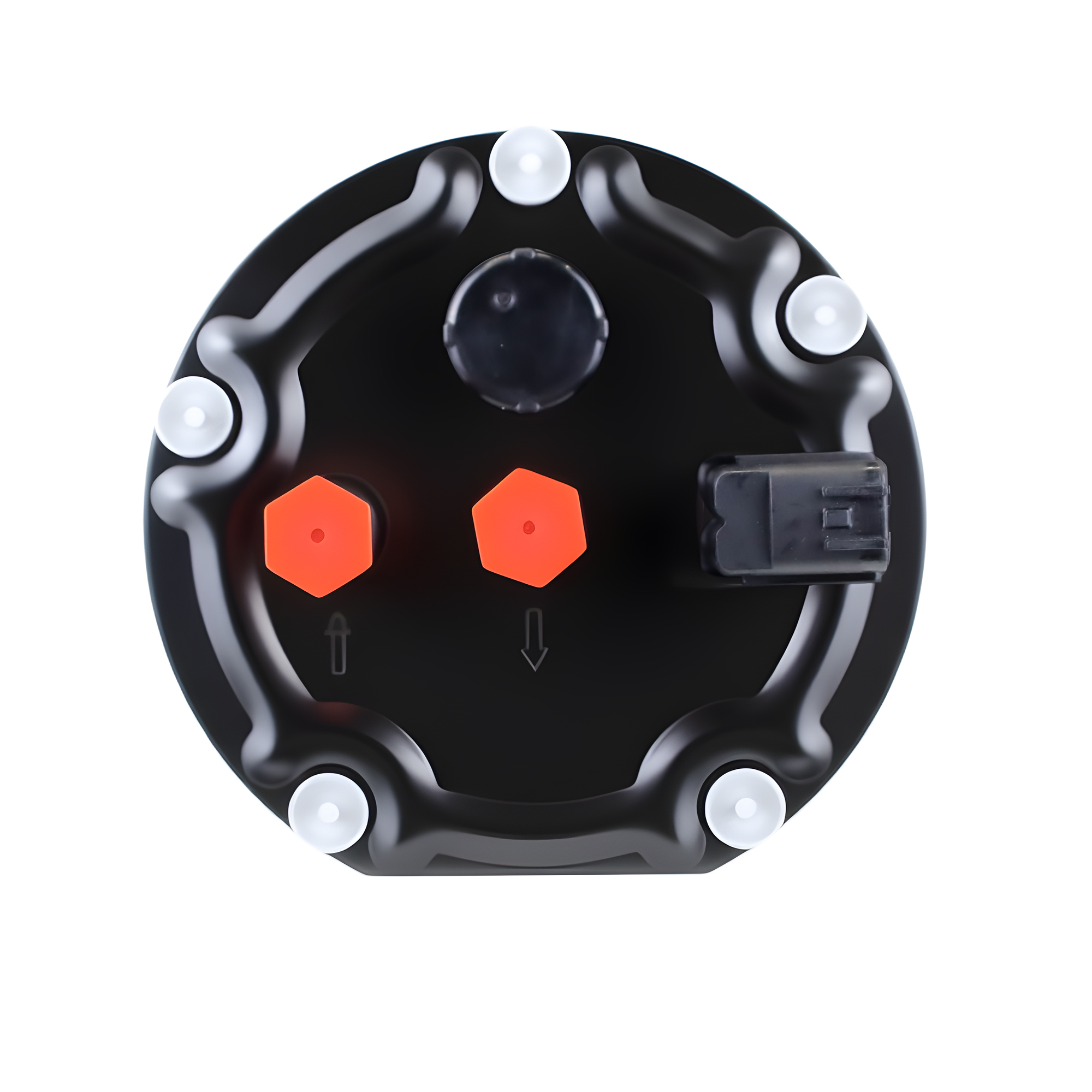
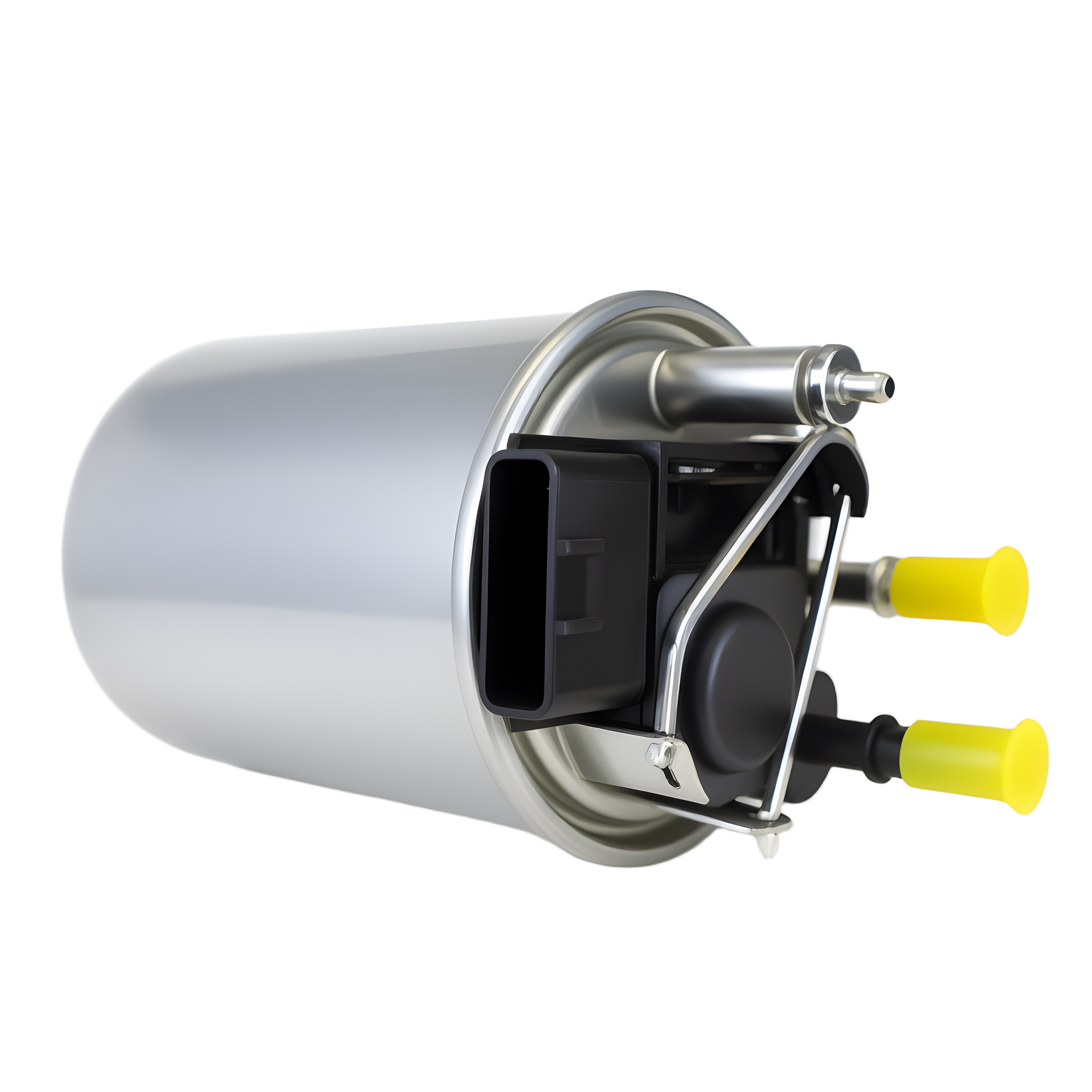
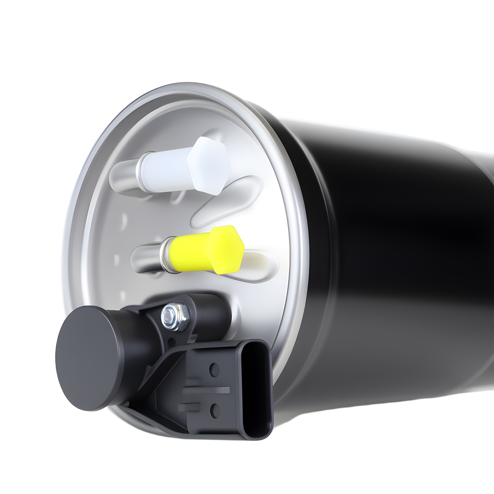
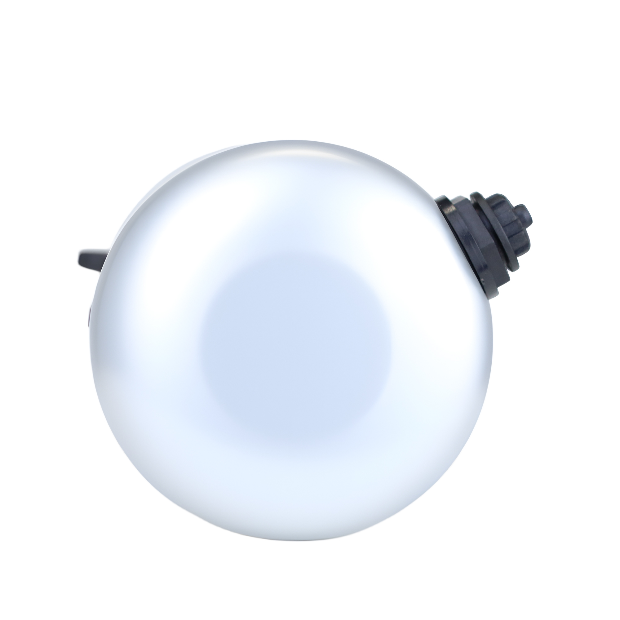
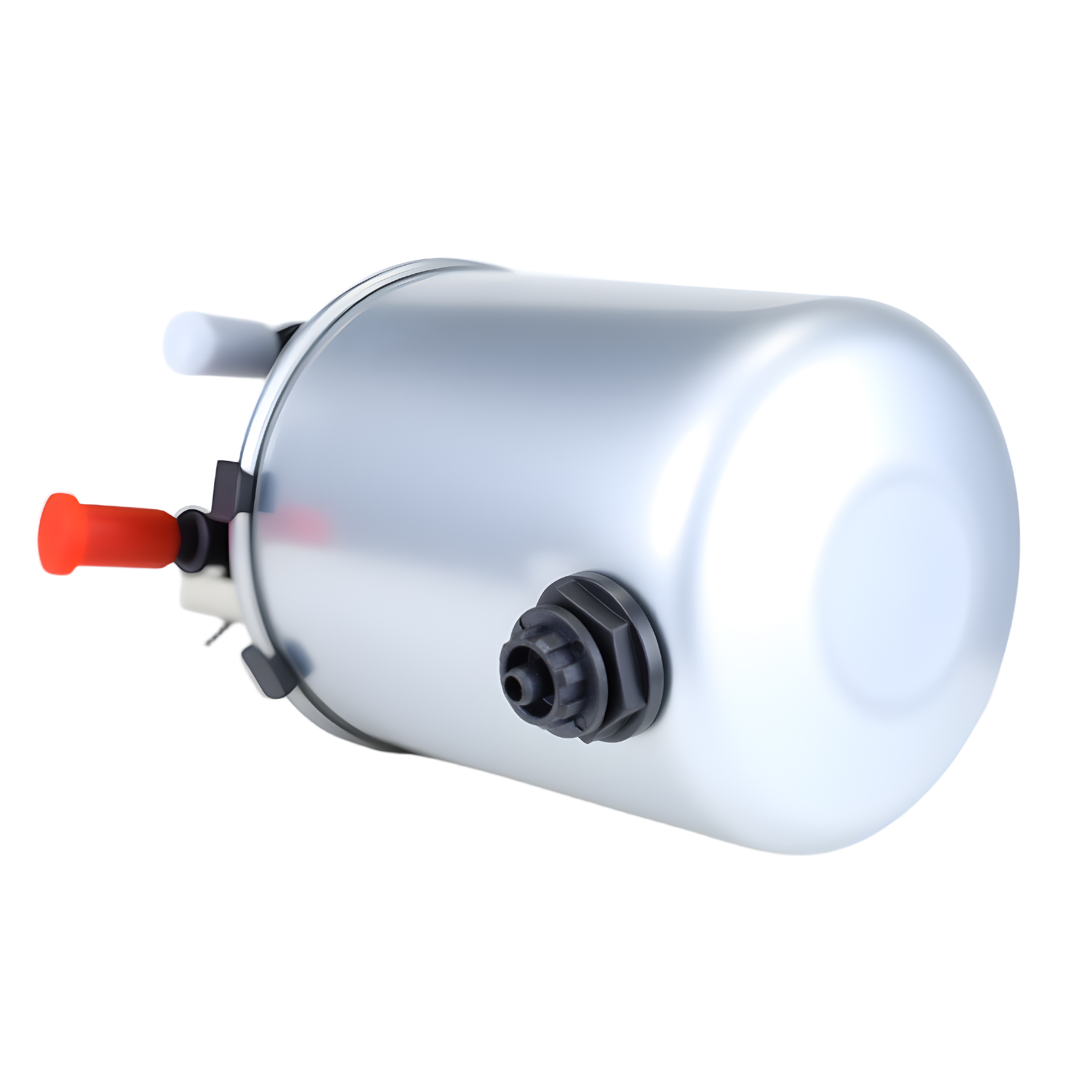
Water detection is integrated differently across diesel platforms. A spin-on assembly may have a molded lower sump with a two-terminal conductivity probe. A cartridge filter may use a serviceable bowl below the element, with a sensor and drain valve retained in the bowl. Some systems combine a heater and sensor module, while others connect the sensor through a short pigtail to a harness branch. Primary chassis-mounted separators and secondary engine filters can coexist, so identify which chamber the ECM actually monitors before draining the first accessible component.
Conductivity sensors commonly use two exposed electrodes. Diesel is relatively nonconductive, while water or conductive residue can bridge the electrodes and change the circuit state. Other designs use a float, capacitance method, or an electronic module that sends a conditioned signal to the ECM. A two-wire sensor is not automatically a simple switch, and a three-wire part is not automatically an analog sensor. The ECM may provide a bias path that makes an open circuit, a short, and a wet condition appear differently. Confirm the design from the diagram and part information before probing.
Do not copy a pinout from a similar-looking filter. Record the connector name, terminal cavity, wire identification where reliable, and controller destination from the correct service literature. If a pigtail has been replaced, compare its cavity positions, terminal locks, seals, and keying with the vehicle harness. A connector can mate mechanically while still carrying the wrong circuit arrangement. That error may leave a persistent warning even though the bowl and sensor are sound.
Capture active and stored codes, freeze-frame information, water-sensor status, fuel temperature, battery or system voltage, and related reference, ground, or fuel-pressure faults. Note whether a scan tool reports a discrete water state, a raw sensor state, or only a diagnostic code. A warning that returns immediately after key-on has a different pattern from one that follows hours of operation or a recent fuel fill. The first pattern often calls for circuit evaluation; the second may justify close attention to fuel condition and separator function.
Confirm the exact lower-bowl and sensor arrangement before testing or specifying a replacement.
Use the published safety and containment method, then take a sample from the lowest drain point of the monitored chamber. Do not draw from a convenient upstream line and assume it represents the bowl. Water normally settles below diesel, but recent movement, return flow, or fueling can disperse droplets. Record the sample appearance, sediment, corrosion particles, odor, and whether it separates after standing. Photograph cracks, haze, residue, damaged seals, and corrosion before cleaning them away.
Inspect the drain valve, cap, bowl threads, O-ring, sensor port, standpipe, and filter-to-bowl interface. A valve that does not seal can create an air or leak complaint, while a distorted bowl can obscure the visual condition and compromise sealing. On a serviceable bowl, confirm that the element is seated as specified and that no O-ring has been pinched, doubled, or installed in the wrong groove. Recent service history is particularly important when a warning begins immediately after an element change.
A distinct water layer or repeated collection from the lowest point supports an actual contamination event. It does not prove why water reached the separator or whether the separator can evacuate it correctly. Conductivity probes respond to the liquid or deposit touching the electrodes. Road salt, coolant, cleaning fluid, metallic debris, corrosion products, and some additive residues can form a conductive bridge without a large volume of clear water. A probe coated with residue can therefore produce a warning in a bowl that looks nearly dry.
Do not pour improvised liquids into the bowl to demonstrate operation. Incompatible fluids can damage seals, contaminate fuel, and create a result with no diagnostic value. Use a simulator, test adapter, or wet-check method only when the exact service information supports it. Otherwise, document what was found in the bowl and continue with circuit checks. A clean-looking sample alone cannot clear an electrical path, just as a code alone cannot prove water was physically present.
Cold conditions can change diesel flow and the appearance of contamination. Condensation may collect during long idle periods, while wax, ice, or gelled material can restrict the drain path. A recent fill or strong return flow can emulsify water and suspend droplets, reducing the sharp interface normally expected in a settled sample. Record ambient and fuel temperature and whether the equipment was recently moved. A warning that changes after warming may relate to fuel condition, drainage, connector moisture, or harness behavior; it should not be assigned to one cause from temperature alone.
Drain sealing, bowl condition, and the sensor port are technical inspection points, not merely cosmetic details.
Inspect the external harness from the sensor to its first secure branch. Look for rubbing on brackets, heat damage, unsupported sections, oil saturation, prior splices, and paths where water can wick into the connector. With the connector unlocked only as required, inspect terminal tension, green corrosion, fretting, damaged cavity seals, and pushed-back terminals. Use proper backprobe tools. Test leads forced into terminals can create a problem that was not present before diagnosis.
For a simple sensor, identify the ECM bias or reference path and the return path. For an active module, identify supply, sensor ground, signal, and any shared reference. Measure at the sensor connector and, when service guidance and access permit, at the corresponding controller-side point. Comparing both ends locates whether an abnormal state follows the sensor, harness, connector, or controller input. A single voltage reading at an unplugged connector is not enough to identify a high-resistance connection or an intermittent short.
Observe the scan-tool state while the connector is secured, and only disconnect or simulate a condition when the manufacturer permits it. A state change that follows connector handling or harness movement but not bowl condition strongly supports an electrical investigation. Check related sensor-reference, supply, and ground codes at the same time. Several shared-circuit faults can cause a water-in-fuel code to be a secondary symptom rather than the primary failure.
Static continuity can pass through a corroded crimp or nearly broken conductor because the meter uses very little current. A voltage-drop comparison, performed in the appropriate circuit state, can expose resistance while the path is biased or loaded. Compare the designated controller ground with the sensor ground, then compare the supply or bias at both ends of its route. Record key state, engine condition, test mode, meter reference, connector position, and whether the warning was active. The acceptable result is defined by the application, not a generic number.
Many ECM inputs deliberately apply a pull-up or pull-down bias so that a normal dry sensor, wet sensor, open circuit, and short circuit create recognizable patterns. That means “low signal” or “high signal” cannot be translated into water without the diagram. A signal rubbed to ground, an open return, moisture bridging terminals, or a reference fault can all imitate the expected wet condition on some architectures. Diagnose the circuit behavior against the published description rather than against a guessed polarity.
Sensor, bowl, seal, drain, and connector provisions must remain compatible when a filter assembly is replaced.
When the warning returns after draining, run two tracks in parallel. The fluid track asks what was present at the sensor location, whether the drain could remove it, and whether contamination or deposits can explain the probe state. The electrical track asks what state the ECM saw, whether that state follows the circuit under documented conditions, and whether it changes with connector or harness handling. The useful answer is the point where the two tracks agree or diverge.
Capture code status, freeze-frame, water-sensor PID or discrete status, fuel temperature, system voltage, and related faults before and after the drain action. Time-align those entries with fueling, cold soak, vibration exposure, connector movement, and any supported circuit isolation step. This avoids relying on memory after the lamp has been cleared. A scan state that changes at the same moment as a connector wiggle is different from a state that changes only after a confirmed wet-bowl condition.
Water found at the drain plus a matching scan state supports investigation of the fuel source, separator retention, and drain function.
A dry bowl with a state that changes during harness movement supports connector or wiring diagnosis.
Shared supply or reference faults should be resolved before the sensor itself is judged.
A stable circuit fault pattern after external checks may justify sensor evaluation through the published method.
Keep removed-component markings, photographs, and contamination observations when a supplier or warranty review may follow. Cleaning the probe or bowl before documenting it can erase the difference between conductive residue and free water. The record should name whether each observation came from the vehicle, the scan tool, the bench, or an incoming part inspection. Those sources answer different questions and should not be blended into one unsupported conclusion.
Remove a water sensor only if the manufacturer identifies it as separately serviceable and provides the removal, seal, torque, and test method. Some sensors are sealed into the bowl or module. Unplanned removal can crack the housing, damage a sealing face, or introduce contamination. Before removal, establish that connector condition, reference or bias, ground path, harness behavior under load, and scan correlation do not explain the warning.
If a supported bench procedure exists, record the part number, terminal identifiers, specified tester or simulator, ambient condition, and result. Do not borrow resistance values from another sensor family. On conductivity probes, surface condition and seal integrity may reveal more than a free-air meter result. If the application offers only an in-vehicle test, retain the assembly and follow that procedure rather than converting a serviceable component into an uncertain one.
The separator is a system, not just a particulate element. The head, element, bowl, standpipe, sensor location, and drain work together to collect, report, and remove water. An aftermarket component that matches the thread and outer diameter but changes the lower seal, bowl interface, or standpipe can affect that function. Repeated complaints across otherwise similar vehicles justify comparison of the installed parts against the exact intended arrangement.
Inspect the valve’s sealing surfaces, actuator, cap, threads, and any tether. Check the bowl for swelling, cracks, clouding, heat damage, and deformation around the sensor port. Examine O-rings for cuts, flattening, wrong cross-section, or debris in the groove. Where a standpipe is used, confirm its presence and position from the service information. A missing or incorrect standpipe can change the collection and drainage path; a wrongly installed seal can create symptoms after routine maintenance.
On combined heater-and-sensor arrangements, confirm that the intended module is installed and that connectors have not been interchanged. Similar connectors are a reason to consult the diagram, not a reason to rely on visual familiarity. If the warning began after an element replacement, compare the new part’s lower interfaces, bowl engagement, and included service items with the removed reference. An apparently minor geometry difference can matter when the sensor monitors the bottom of a water sump.
For sourcing, start with the OE reference and application data, then verify the complete function: vehicle or engine range, filter-head family, bowl type, heater provision, sensor style, connector keying, drain arrangement, seals, and mounting interfaces. An OE reference identifies the target; it does not represent an aftermarket item as genuine OE. A broad “fits” claim is inadequate when water detection is part of the operating requirement.
Receiving teams should compare accessible details against the approved technical sample or documented original: label identity, thread and seal geometry, bowl mating profile, drain design, sensor port, connector keying, and kit contents. Confirm packaging and lot identification as well. A variance belongs in technical review before installation. It is less costly to quarantine a questionable batch than to create a pattern of field warnings across a mixed fleet.
Incoming comparison should cover water-management interfaces, not only outer dimensions or a catalog number.
Once diagnosis identifies the affected function, specify the required component clearly: complete filter, cartridge, bowl, drain assembly, sensor, seal kit, or combined module. Include the original reference, verified aftermarket cross-references, engine or vehicle details, installed filter-head or bowl reference, photographs of labels and connectors, and any known fitment restrictions. If an electrical fault is involved, include the code description, terminal count, connector views, and results of supported checks so a supplier does not quote a visually similar but incompatible part.
Engine, vehicle or equipment serial range, duty cycle, and the installed separator configuration.
OE-reference number, verified cross-references, requested component scope, and photographs of visible interfaces.
Sensor and heater provision, drain style, bowl details, seal package, connector keying, and confirmed fitment constraints.
Quantity, destination, packaging, lot traceability, documentation, and required incoming inspection comparison.
A fuel filter item example can be compared with the application record, but the quote should remain tied to the documented separator and sensor function. Ask for the basis of fitment and notification of revisions affecting the bowl, sensor port, connector, or sealing package. That protects the workshop from a substitute that fits physically while changing a critical water-management feature.
After the required service, follow the manufacturer’s priming, leak-check, and fault-clearing procedure. Verify the scan status and related codes, then observe the machine through the conditions that previously produced the warning when safe and practical. A cleared lamp does not settle an intermittent connector issue or a conductive deposit. Record installed parts, lot identity, sample observations, circuit findings, and final scan status in the maintenance record.
Where actual contamination was found, consider the fuel source, storage practice, tank condition, ingress routes, and other equipment supplied from the same source. Where the cause was electrical, retain the relevant pigtail or sensor when appropriate and record the exact fault location. This distinction gives fleet managers and distributors useful evidence for follow-up, rather than a vague statement that a fuel filter was changed.
Traceable part identity and documented fitment help prevent repeat water-sensor complaints after procurement.
A defensible diagnosis connects the separator condition, the documented circuit behavior, and the ECM record. Free water, conductive deposits, connector corrosion, wiring damage, an incorrect lower module, and a failed sensor can all create the same dashboard warning. The correct response follows the evidence rather than the easiest component to replace.
For commercial support, review Elecdurauto company information, send verified application and component details through the B2B contact page, or use the Elecdurauto parts catalog to locate the relevant family. Accurate OE-reference matching, inspection findings, and fault history turn a warning event into a precise aftermarket inquiry.