ELECDURA NETWORK

Your Whole New Supply Chain For Heavy-Duty Parts
Whatsapp:
+86 18915027366
Phone:
+86 18915027366
Views: 0 Author: Site Editor Publish Time: 2026-08-25 Origin: Site
When a heavy-duty alternator appears to undercharge, the alternator is only one part of the charging path. A voltage-drop test made while the system is loaded can reveal loss between the alternator B+ output, batteries, grounding points, and major distribution connections. That evidence is particularly valuable after an alternator replacement, when a fleet needs to know whether the remaining complaint is a component defect, an installation issue, or a vehicle-side resistance problem.
Start by confirming the charging-unit configuration. The heavy-duty alternator category is organised for B2B matching by application and part identity; a replacement must still be checked for mounting, output class, terminal layout, pulley arrangement, and any required sense or communication connections. A correct-looking alternator can be wrong for the wiring architecture that it is asked to serve.
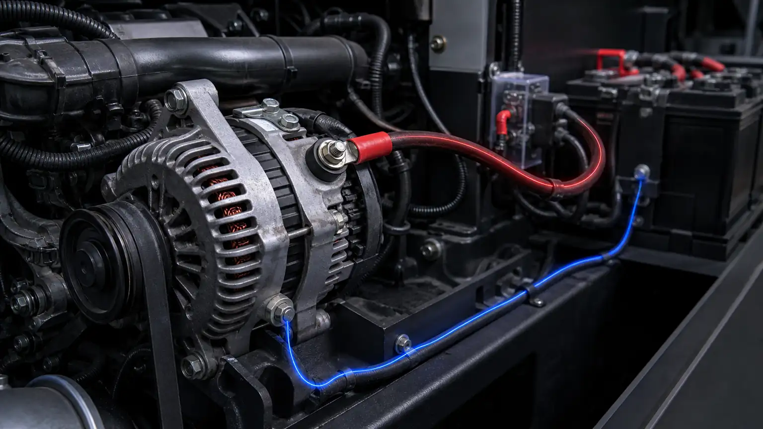
Identify the output cable route, fusible protection, battery connection, and engine ground return for a loaded charging-system test.
A voltage-drop reading compares two points in a working circuit. In a charging-system audit, the positive-side measurement commonly compares the alternator B+ output with the battery positive connection. The ground-side measurement compares an approved alternator case or ground point with battery negative. Each reading represents the loss across the path between those points while current is flowing.
These readings do not, by themselves, prove alternator output capability. They tell the technician where voltage is being consumed outside the intended load. A high reading can point to a corroded terminal, loose stud, overheated cable, damaged fusible link, poor engine-to-frame bond, or an improperly routed conductor. The applicable vehicle and alternator maker procedure determines the test load and acceptance criteria.
At idle with modest electrical demand, a weak cable connection may appear normal. Add the loads that matter to the fleet—lighting, blower, liftgate, refrigeration support, battery recovery after starts, or auxiliary equipment—and the resistance becomes more visible. The audit should capture the operating state, engine speed, electrical loads, battery condition, and ambient temperature so that a later comparison is meaningful.
Follow the vehicle manufacturer’s safety process. Secure the vehicle, avoid moving belts and fans, and keep meter leads clear of hot or rotating parts. Test batteries first according to their manufacturer’s instructions. A battery bank with a failed or deeply discharged battery can force abnormal charging behaviour and lead to an incorrect diagnosis.
Take photographs of the B+ output, battery posts, main junctions, negative battery cables, alternator mounts, and engine-to-frame grounds. Record the alternator label and all visible connection identifiers. Photographing first helps distinguish a poor connection from a connection that was altered during the repair.
Use the relevant service procedure to establish a controlled demand. The report should state which loads were applied and whether any special test equipment was used. Do not create a generic “full-load” label when the actual electrical demand is unknown. For a distribution program, a repeatable load profile gives the warranty team a practical basis for comparing similar claims.
Probe on conductive terminals and approved ground surfaces, not through paint, plating damage, or a loose auxiliary lead. If access requires a remote junction, describe the actual endpoints because they define which portion of the circuit is being measured. Good probe placement is more valuable than a highly precise number attached to the wrong section.
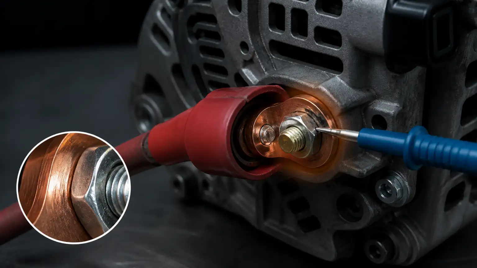
Show probe access and the inspection points where a loose nut, heat damage, or undersized lug can add loss.
Measure from the alternator B+ output to the battery-positive point specified by the vehicle procedure while the charging system is carrying the planned load. If the loss is excessive for the applicable specification, divide the path into smaller sections: B+ stud to cable lug, cable to junction, junction to battery disconnect, and disconnect to battery post. The section with the abnormal loss should be inspected before the alternator is removed.
Look for heat marks around a stud, a discoloured lug barrel, loosened hardware, undersized replacement cable, a fused connection that has been bypassed incorrectly, or a cable that is chafed beneath a clamp. Vibration and high current can damage a connection internally before external corrosion becomes obvious. A buyer should preserve the failed connection and the corresponding reading when requesting technical support.
Some heavy-duty electrical systems route alternator output through disconnects, protection devices, battery-management components, or remote distribution posts. Treat each intended component as part of the measured path. Do not bypass safety devices to “prove” an alternator, and do not use a workaround as a permanent repair unless the equipment manufacturer explicitly authorises it.
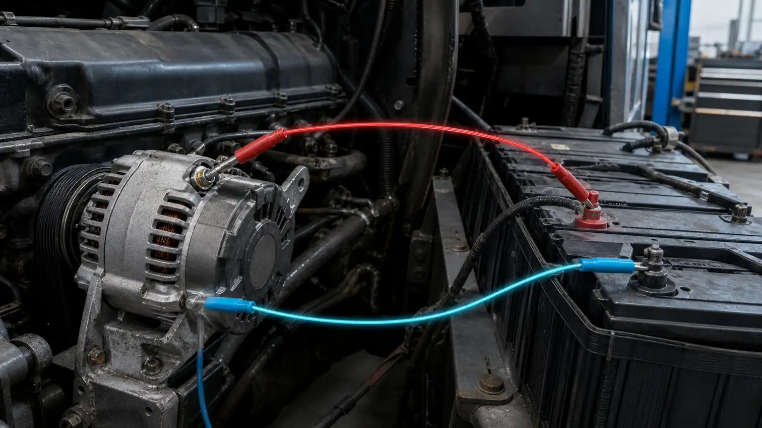
Illustrate two measurement pairs without duplicating the starter article's visual approach.
A ground path is often assumed to be good because the alternator is bolted to the engine. That assumption overlooks painted brackets, oxidised mounting faces, loose engine grounds, damaged frame straps, and battery-negative connections. Under charging load, these points can lose enough voltage to confuse regulator behaviour or leave the battery bank undercharged.
With the prescribed load applied, compare a designated alternator case or ground point to the battery-negative point. If the reading indicates an unacceptable loss, isolate the path progressively. Check alternator mounting, engine ground straps, frame bonds, and battery-negative terminations. Repair the actual fault and re-test with the same load profile rather than declaring success after a visual clean-up.
A high ground-side loss most often directs attention to the return path, not directly to the alternator’s internal components. The sequence matters: establish battery condition, verify positive and negative paths, then evaluate alternator performance against its own procedure. This order avoids replacing a charging unit that was never supplied with a reliable electrical reference.
Some alternator systems include remote sense, ignition, warning-lamp, field, communication, or battery-management connections. These circuits affect how the system is controlled, but they should not be confused with the high-current B+ and ground audit. Identify each terminal from the exact wiring diagram and alternator documentation before probing it.
If the system uses remote sensing, record the terminal identity, route, fuse or protection component, and measured condition separately from the main cable-loss results. Do not add or omit a jumper merely to obtain a charging reading. A sense-circuit repair must follow the original design and the manufacturer’s instructions, particularly where electronic battery monitoring is present.
A useful B2B record includes the vehicle or equipment identity, old and replacement alternator labels, voltage system, load profile, B+ test endpoints, ground test endpoints, readings, images, repairs, and re-test results. It should also capture any alternator terminal, pulley, mounting, or connector differences found during installation.
When the audit supports a replacement request, send the evidence through the Elecdurauto B2B quotation contact page with the application details and required quantity. This helps the matching process focus on the correct unit configuration rather than asking a supplier to infer the problem from “not charging” alone.
For fleets, repeated voltage-drop findings can identify cable-routing, corrosion-protection, or maintenance-process issues before they create a pattern of alternator returns. Group records by vehicle platform, operating environment, and path location. The goal is to make the electrical system reliable, not merely to increase the number of components replaced.
Output capability and voltage delivery are related but different questions. An alternator may be capable of producing current while resistance in the B+ or ground path prevents the battery bank from receiving the intended charging voltage. Conversely, a sound cable path does not prove that an alternator is meeting its rated performance. The diagnostic record should show which question was evaluated and which tool or manufacturer procedure was used.
When the relevant procedure calls for it, record voltage at the alternator terminals and at the battery terminals under the same electrical load. The difference may point to a delivery-path issue, while the individual readings still need interpretation according to the exact system design. Avoid declaring an alternator “overcharging” or “undercharging” from a single location when remote sensing, battery management, temperature compensation, or a nonstandard battery configuration may be present.
A voltage-drop audit does not replace inspection of the mechanical drive. Follow the equipment procedure to check belt condition, tensioning system, pulley alignment, mounting hardware, and abnormal noise. A slipping belt, damaged pulley, or loose mount can produce a charging complaint that is not fixed by changing a cable or alternator. Record those findings separately so a B+ result is not misused as an explanation for every symptom.
When a connection or cable is repaired, re-test the same endpoints with the same controlled load profile. Do not change multiple sections at once if the objective is to identify the original fault. A staged record shows whether the correction changed the measured loss and makes it easier to recognise an additional issue that was hidden by the first fault.
Before fitting an alternator, compare mounting dimensions, pulley, belt type, B+ terminal position, sense or auxiliary terminals, connector keying, and any communication requirements. After fitting, ensure that cable routing, strain relief, terminal protection, and torque follow the applicable instructions. A correct catalog number does not authorise a substitute connector or an altered cable route.
If a unit must be returned, retain the original label, installation photographs, B+ and ground audit results, battery test record, and details of the vehicle load condition. Do not erase diagnostic data by replacing cables and discarding the original connection before it is documented. This evidence helps a technical team distinguish an internal product concern from an external-system concern.
For a heavy-duty distributor, the audit record can inform inventory decisions. If several claims on one platform trace to a shared cable route or terminal corrosion, adding more alternator stock will not resolve the underlying service demand. If the electrical path is repeatedly proven and a specific alternator configuration fails in service, the record supports a more focused review of the application, operating load, and replacement specification.
This evidence-led approach also makes quotations better. Instead of asking for a “high-output alternator” without context, a buyer can provide the current unit label, electrical architecture, accessory load, pulley and belt details, connection requirements, and measured system findings. That is a more reliable basis for matching than broad application names alone.
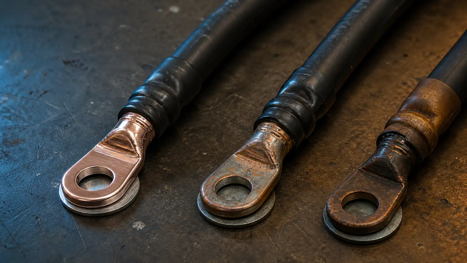
Connect abnormal voltage drop to real inspection evidence such as discoloration, fretting, or softened insulation.
Repeated alternator replacement can conceal a recurring installation or environment issue. Salt exposure, loose cable support, add-on loads, poorly protected junctions, and battery service practices can all change the resistance seen by the charging system. A repair report should identify any non-original electrical additions and any evidence of vibration, moisture entry, or abrasion near the tested path.
Once the measurement is recorded, inspect the physical connection with the system safely isolated according to the manufacturer procedure. Check terminal seating, retention, fastener condition, corrosion, cable support, and strain relief. Do not retorque or clean the connection before recording its original condition, because the alteration can make later review impossible.
A higher-output alternator may have a legitimate application when the vehicle design and supplier specification support it. It is not a repair for a high-resistance cable, failing battery, or undersized circuit. Upgrading hardware without reviewing cable sizing, connectors, belt drive, and battery management can create a different problem. The sourcing record should therefore state whether the goal is exact replacement or a documented system change.
A technician needs precise endpoints and a reproducible load condition. A buyer needs the old-unit reference, the requested configuration, evidence of physical fit, and a clear statement of what has been ruled out. One well-organised record can serve both audiences if it separates observations from conclusions and keeps the test data beside the component identity.
For multi-site service networks, a short template with controlled fields is often better than free-form notes. It can prompt for B+ endpoints, ground endpoints, battery condition, alternator label, load profile, auxiliary terminals present, repair made, and re-test result. The template should guide good evidence collection without imposing a single diagnostic limit on every vehicle.
When evaluating a multi-battery vehicle, describe the battery-bank layout and the chosen battery-side test point. A delivery-path reading taken at one battery may not represent a remote battery, a crossover cable, or a protected distribution node. The vehicle wiring diagram and service procedure determine the correct points. Clear naming prevents a later reviewer from treating readings from different locations as though they were directly comparable.
Allow the system to reach the condition required by the test method before recording a result. Temperature, engine speed, battery state, and switched loads may affect how the regulator and the electrical network behave. The report should identify the condition without pretending that one short observation represents every operating scenario. If a complaint occurs only with a particular auxiliary load, include that fact in the diagnostic brief.
After a B+ or ground repair, inspect cable support and protection along the full repaired section. A freshly tightened terminal can pass the immediate re-test but fail later if the cable remains unsupported near vibration, heat, or a sharp edge. Use the original routing and protective components where the vehicle design requires them, and record any approved change rather than leaving it to a future installer to interpret.
When a replacement alternator is supplied, retain the old-unit reference and the exact terminal-side photographs until the vehicle has completed its verification process. This avoids a common sourcing mistake: a similar case mounting is treated as a match even though the B+ position, remote-sense arrangement, or auxiliary connector differs. A configuration difference should be resolved before connection, not after a charging complaint is reported.
Where an application uses an external battery disconnect or a serviceable charging junction, record whether that component was in its normal operating state during the test. A test result captured across an open, bypassed, or temporarily altered path cannot be used as a normal in-service reference. The final record should describe the actual system configuration at the time of measurement.
For a vehicle that operates with high intermittent loads, repeat the approved audit under the condition that reproduces the complaint where safe and specified. A report that records only a low-demand condition may miss the path resistance that becomes important when the auxiliary equipment is active.
A B+ and ground-side load audit gives the charging system a clear diagnostic structure. Measure the correct endpoints under a documented load, split an abnormal path into smaller sections, and distinguish cable loss from alternator performance. For heavy-duty buyers, that discipline leads to better replacement matching, clearer warranty evidence, and fewer repeat charging complaints.