ELECDURA NETWORK

Your Whole New Supply Chain For Heavy-Duty Parts
Whatsapp:
+86 18915027366
Phone:
+86 18915027366
Views: 0 Author: Site Editor Publish Time: 2026-08-24 Origin: Site
Cold weather exposes a solenoid valve in a way a warm, lightly loaded bench often cannot. When hydraulic oil thickens, the valve must overcome higher drag, changing pressure forces, and restricted return flow before the commanded function appears at the actuator. A pneumatic valve can face an analogous delay when pilot passages, exhaust restrictions, or moisture affect the differential it must move against. The familiar symptom is simple—slow engagement, delayed release, weak pressure build, or an intermittent cold-start fault—but the cause may sit in the coil circuit, the spool, the oil, or the machine plumbing.
For distributors, fleets, and equipment service teams, response-time testing is most useful when it answers a specific application question: does this valve respond consistently under the same cold, loaded conditions the machine sees? The Elecdurauto solenoid valve category can help organize product families during that discussion, but the operating condition and OE reference still decide whether a comparison is valid. This guide explains how to separate electrical delay from hydraulic delay without assuming universal time, temperature, viscosity, voltage, or pressure limits.
The goal is not to chase one attractive number. It is to create synchronized evidence of the command, coil current, valve movement, and hydraulic outcome, then use that record to make a practical sourcing or maintenance decision.
A valve’s advertised or observed response time can cover several different events. Start at the command edge: the instant the controller, switch, or bench supply tells the coil to energize or de-energize. Electrical delay follows as voltage reaches the coil and current rises through the winding. Magnetic force then builds enough to move the armature or pilot. Mechanical delay covers the breakaway and travel of the armature, poppet, or spool. Finally, hydraulic delay continues until pressure, flow, or actuator motion reaches the defined functional point.
Those intervals may overlap, but they should not be treated as one mystery interval. A crisp current ramp followed by a late pressure transition points to a different investigation than a delayed current ramp with normal movement after energization. Release matters too. A valve may pull in reliably but hold pressure, drain slowly, or return late because of trapped volume, return restriction, spool friction, or the controller’s suppression strategy.
Define the start point from the actual electrical command, not from a technician’s hand motion or a relay click. Define the end point from the function that matters: a pressure crossing, a verified flow change, a spool-position signal, an actuator movement, or a switch state. For a directional hydraulic valve, the useful endpoint may be pressure appearing at the work port. For a proportional or pilot-operated design, it may be a repeatable point on the pressure or flow curve. For a pneumatic valve, it may be pilot pressure or downstream cylinder motion.
State the function in plain language beside the trace. “Command to A-port pressure rise under cold oil” is clearer than “valve response.” It also prevents a procurement discussion from comparing a direct-acting cartridge to a pilot-operated assembly as if their timing labels represented the same event.
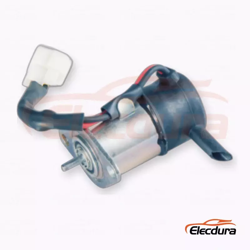
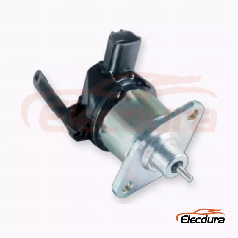
Use the physical valve reference to confirm connector, port, and mounting details before assigning a test function.
Cold-oil testing starts with conditioning, not with an arbitrary freezer setting. Record the fluid type, grade, service condition, and any available viscosity-versus-temperature information from the fluid supplier. Measure oil temperature close enough to the valve inlet to represent what the spool sees. Also record valve body temperature and ambient temperature when they can differ materially. A valve pulled from a warm shop and filled with cold oil is not the same condition as a valve, manifold, and reservoir that have soaked together.
Allow time for the thermal state to stabilize, then document how that decision was made. In a hydraulic circuit, circulation may warm a small passage or the valve body before the reservoir reflects the same condition. In a pneumatic installation, icing, condensate, and cold seals can change the behavior even when air temperature alone looks controlled. The correct conditioning method is the one that represents the intended machine duty, not a generic laboratory ritual.
Higher oil viscosity can slow a pressure rise through restrictions, increase shear in spool lands and clearances, and alter damping in a pilot stage. It can also make a return path look more restrictive than it is when warm. That does not prove the valve is defective. It means the test must show inlet pressure, the relevant outlet or work-port pressure, return or tank pressure where applicable, and the commanded flow path.
Capture the fluid condition as part of the result. Fresh oil, used oil, a mixed top-up, and fluid with visible contamination can produce different cold behavior. If a fleet’s concern is a morning start after long parking, compare that case with a stabilized operating condition instead of treating a single cooled sample as the whole story.
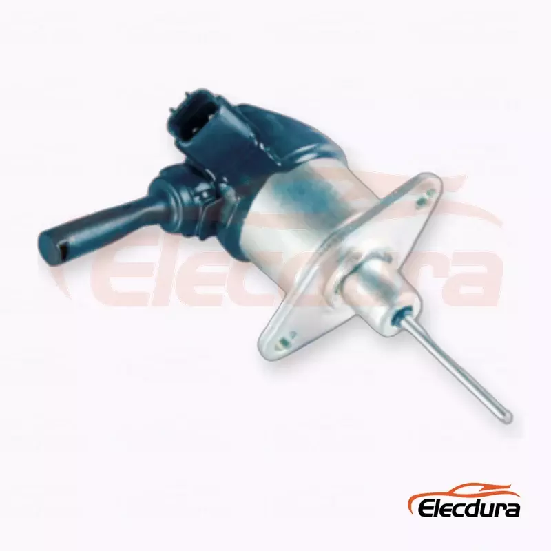
A documented valve configuration helps keep cold-soak results tied to the correct hydraulic arrangement.
The most revealing cold-load test captures the electrical command, coil voltage, coil current, and hydraulic response on a common time base. Use instruments with a known trigger relationship rather than trying to align separate screenshots after the event. A shared data-acquisition trigger is ideal; a documented trigger pulse recorded by every channel can also work. The point is to know whether a difference belongs to the valve or to the clocks.
Measure coil voltage at the coil connector under load, not only at the power source. Measure current with a method suited to the waveform and expected range. Voltage tells whether the winding received the command it was supposed to receive; current shows how the inductive load actually responded. Record the controller type, any PWM strategy, and the driver or bench supply configuration. A current-controlled driver and a simple switched battery feed may create different pull-in behavior even on the same valve.
A pressure transducer placed only at the supply can miss a delayed work-port transition. Select channels around the event of interest: inlet and outlet, pilot and main stage, or work port and return, as the circuit requires. Add flow measurement when it is necessary to show that a pressure change corresponds to usable flow. A spool-position sensor is valuable where the valve design permits it, but pressure and flow still show whether movement became machine function.
Sensor response and plumbing volume matter. Long small-bore lines, trapped air, a remote transducer, or a heavily damped pressure port can add apparent delay. Before blaming the valve, verify the signal path with a repeatable reference event. Note sampling rate, sensor range, calibration status, and the channel used as the timing trigger. These practical details protect a distributor from making a purchase decision on a trace that was slowed by its own test plumbing.
A normal-looking command with a slow or incomplete current rise can indicate supply loss, excess harness resistance, a weak driver, an incorrect coil, or a problem in the connector. A current profile that reaches its expected shape promptly while the pressure response arrives late directs attention toward mechanical or hydraulic resistance. Conversely, a pressure response that begins on time but settles poorly can suggest downstream restriction, leakage, air, or load behavior rather than late spool movement.
Keep the raw traces. A single calculated number cannot show a stepped current ramp, a bounce at pull-in, a delayed pilot transition, or a pressure overshoot. Those shapes are often what separate an electrical fault from a cold-fluid effect.
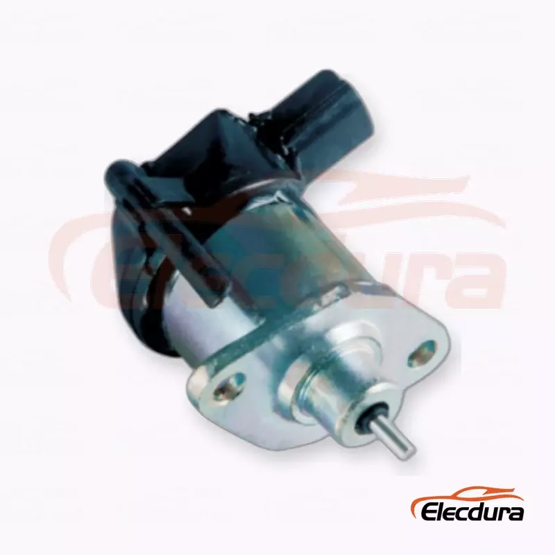
Electrical and hydraulic timing must be recorded from the installed valve function, not inferred from appearance alone.
Cold response is strongly affected by the pressure differential the moving element must overcome. Test the commanded direction under the inlet pressure, work-port load, and return condition that represent the application. For normally closed, normally open, direct-acting, pilot-operated, cartridge, and manifold-mounted valves, the important differential is not always at the same port. Review the circuit symbol and the OE application before choosing the pressure channels.
Return restriction deserves special attention. Cold oil through a filter, cooler, hose, tank line, or shared manifold can raise backpressure and delay a spool’s return or a pilot stage’s exhaust. A test that measures only supply pressure may label that behavior as a slow valve. Recording return pressure and comparing it with the warm reference can reveal the difference. The same principle applies to pneumatic exhaust restrictions and pilot vent paths.
A useful test matrix varies only the factors that genuinely matter to the installation: cold and stabilized condition, representative supply states, representative return restriction, commanded direction, and the specified electrical drive. It may include a defined dwell between cycles and a controlled sequence that does not overheat the coil. The exact points belong to the valve, fluid, machine, and customer’s duty; they should not be copied from an unrelated product sheet.
Record the initial thermal state and the condition after cycling.
Keep the coil drive and harness configuration constant while pressure variables change.
Identify the start and end event used for each command direction.
Repeat the warm reference after the cold series when coil heating or fluid warming could have changed the result.
This structure makes it possible to see whether delay follows oil temperature, pressure differential, return restriction, voltage delivery, or a combination. It also keeps “cold start” separate from a valve that has been energized repeatedly and warmed by its own coil.
First-cycle behavior is often more informative than the average of many quick repetitions. Varnish, fine particles, seal drag, corrosion, or a marginal armature can make the first cold shift late and the following shifts faster. That pattern is different from a coil that receives late voltage on every command. Record first actuation after soak, subsequent cycles at the same condition, and the response after the valve returns toward ambient or stabilized operation.
Test both directions where the application uses both. A spool can shift one way promptly and return slowly because the force balance, spring, pilot path, or return pressure is different. Directional hysteresis should be described as a difference between defined traces under matched conditions, not as a vague impression that the valve “sticks.” If disassembly is necessary, preserve the as-received condition first; cleaning away debris or varnish may remove the evidence that explained the cold delay.
Inspect the valve screen, cavity, fluid sample, filters, and related components as the application permits. Metallic particles, seal fragments, and varnish can point to different upstream causes. But do not turn a visible speck into a conclusion without the timing data. A contaminated valve may still have an electrical command issue, and a clean-looking valve may still bind under a pressure differential that was absent on the bench.
For repeatability, use the same fluid cleanliness state across comparison samples whenever possible. A replacement valve tested in cleaner oil than the removed unit is not a direct response-time comparison. Describe the condition honestly in the report and use it to decide whether the corrective action is a valve replacement, circuit cleaning, filtration work, driver repair, or a combination.
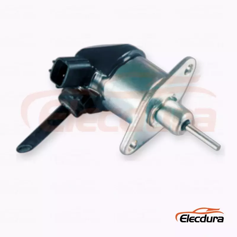
Use a traceable sample identity when comparing first-cycle delay, repeated cycling, and contamination findings.
A good diagnostic conclusion names the first event that diverged from the warm or known-good reference. If the command arrives late, investigate the controller, switch, relay, harness, connector, ground path, and supply condition. If command voltage arrives but current does not rise as expected, investigate the coil and its circuit. If voltage and current are timely while spool movement or pressure response is late, investigate the valve mechanics, pressure differential, return path, fluid condition, and load.
De-energization requires the same discipline. Flyback suppression, PWM decay behavior, and controller strategy can extend current decay after the command is removed. A technician may see a slow hydraulic release and condemn the valve even though the coil was intentionally held magnetized by the driver. Capture the command-off edge, current decay, and hydraulic release together before changing the part.
Repeated duty warms the coil, changes winding resistance, and can alter available magnetic force under a given drive method. It can also warm the nearby fluid and reduce mechanical resistance. Log the energization period, off time, sequence, and surface or body temperature where practical. A cold-start result and a stabilized result answer different questions; both can be useful, but neither should be substituted for the other.
Stay within the valve’s stated duty capability and the test equipment’s limits. The purpose is to reproduce the application, not to force a failure through an excessive bench cycle. When a customer needs a special endurance or low-temperature qualification, request the applicable specification rather than presenting a general cold-oil trace as proof of every condition.
Use multiple cycles so that the report describes repeatability instead of one memorable event. Keep the same start condition, command method, pressure state, and endpoint definition for each run in a set. Review spread in the electrical and hydraulic intervals separately. A wide spread in mechanical or pressure response with stable electrical timing is meaningful; a wide spread in command voltage makes the hydraulic comparison less conclusive.
Then compare cold start with stabilized duty. The first test can represent the machine after overnight parking, while the second can represent normal operation after fluid circulation and coil heating. If the application cycles frequently, include a duty sequence that reflects its real use pattern. If it holds energized for long periods, assess the response after the declared hold condition rather than only after a short pulse.
Hysteresis is not merely a technical word for inconsistent results. In this context, it can describe a valve whose response depends on direction, prior temperature, previous cycle, or the path used to reach the pressure state. The practical question is whether the difference changes machine behavior or moves outside the customer’s stated requirement. Without that application requirement, the test can identify a pattern but should not invent a universal pass/fail threshold.
For fleet validation, keep at least one documented reference sample or a complete reference trace tied to the confirmed application. For distribution, compare incoming samples to that controlled reference only when coil rating, connector, porting, seal material, function, and operating conditions match. A catalog cross-reference alone is not enough to establish dynamic equivalence.
Response-time testing becomes commercially valuable when it travels with the application identity. Start with the OE number or the customer’s documented reference, then collect the machine or vehicle model, system function, valve location, connector, port type, mounting arrangement, coil marking, fluid or air medium, and operating complaint. Add clear photos and measured interface details when the OE reference is incomplete. This prevents a similar-looking valve from entering the quote because its dimensions appear close.
For a related product reference, the Caterpillar 109-4591 hydraulic solenoid valve listing illustrates the kind of named application information that should be checked against the customer’s own machine data. It is not a substitute for confirming the customer’s OE number, circuit role, and fitment. Buyers should ask whether the supplier can identify the exact requested variant and what information supports that match.
OE number, customer reference, machine model, and the valve’s function in the circuit.
Photos of markings, connector, ports, mounting features, and the removed part beside a scale where useful.
Coil rating and drive description, including any controller or PWM details known from the machine.
The fluid or pneumatic medium, cold-start complaint, representative pressure conditions, and response endpoint used in the test.
Required quantity, target market, packaging or labeling needs, and whether a sample comparison is requested.
Incoming inspection should focus on the characteristics that can change dynamic behavior: correct identity, connector and port interface, coil marking, visible construction, and any agreed functional comparison under a defined condition. A fleet may need a small application-specific validation before a wider purchase; a distributor may need a controlled sample review before stocking a new source. The scope should follow the business risk and the application, not a generic checklist.
RFQ review should match the tested valve identity to the customer’s OE reference and installation details.
A cold-oil response trace is valuable because it keeps a complex symptom tied to its physical sequence. It can show that the command was late, the current ramp was abnormal, the spool hesitated, the return path raised backpressure, or the valve behaved consistently but the application requirement calls for another design. That clarity supports a cleaner repair decision and a more precise purchase inquiry.
For supplier background, buyers can review Elecdurauto company information, send application details and the test context through the B2B contact page, or browse the Elecdurauto heavy-duty parts catalog. The strongest inquiry names the OE reference, installation, and measured condition, then asks for a match that can be evaluated against those facts.