ELECDURA NETWORK

Your Whole New Supply Chain For Heavy-Duty Parts
Whatsapp:
+86 18915027366
Phone:
+86 18915027366
Views: 0 Author: Elecdura Publish Time: 2026-09-04 Origin: Site
A heavy-duty diesel underboost complaint should not send the buyer straight to a replacement turbocharger. First confirm that measured boost is genuinely below the engine maker's target under a repeatable load. Then check the intake and charge-air path, exhaust restriction and leakage, fuel and air-management inputs, actuator command and mechanical travel. Inspect the turbocharger only after those external causes are controlled. Replace the unit when identity and system evidence point to damaged wheels, excessive wear, seized geometry or another non-serviceable turbo fault—not merely because the fault code contains “boost.”
This guide is for fleet technicians, rebuilders, distributors and sourcing teams that need a defensible test order and a useful failure record. Applicable limits, commanded positions and test loads must come from the engine or vehicle service information.
Start with the exact complaint: low power, black smoke, slow boost response, derate, a pressure-deviation code, or a combination. Record engine model and serial number, calibration or software level where available, operating hours or distance, recent work, ambient conditions, fuel condition and the load event that produces the symptom. A graph captured during an unloaded throttle snap does not represent every heavy-duty duty cycle.
Compare desired and actual boost or manifold pressure only when the scan parameter definitions are understood. Some systems report absolute pressure, others gauge pressure; barometric pressure and altitude therefore matter. Capture engine speed, load or fueling request, charge-air temperature, exhaust restriction data if available, commanded and actual actuator position, EGR state and relevant fault codes on the same time base. A single maximum value without the preceding response curve can hide a lag, intermittent leak or control event.
If the complaint cannot be reproduced safely, do not manufacture a conclusion. Record it as intermittent, preserve freeze-frame and driver evidence, and continue with non-invasive inspection. The wastegate actuator pressure-testing guide is useful when the evidence points specifically to a pressure-operated actuator; this article covers the wider underboost system.
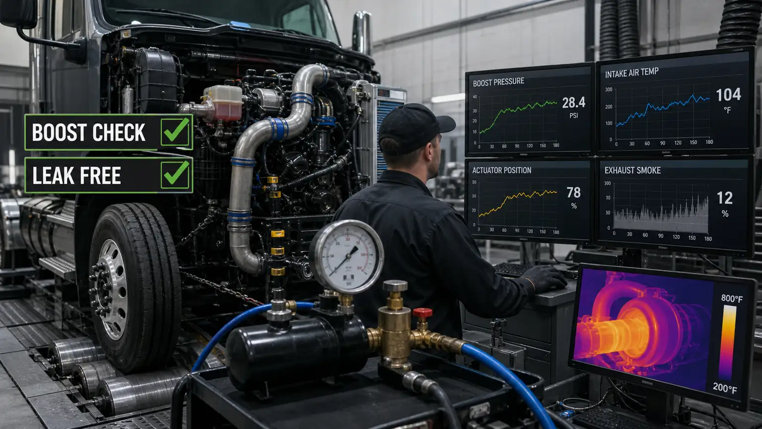
A repeatable load event and synchronized data turn “low power” into a testable pressure-response problem. The staged image supplies no model-specific target.
Inspect the air cleaner, restriction indicator, inlet duct, clamps and compressor inlet for blockage, collapse, loose connections or foreign-object evidence. Continue from the compressor outlet through every boot, pipe, charge-air cooler, sensor port and intake manifold joint. Oil film alone does not locate a leak, and a hose that looks acceptable at rest can open under pressure or engine movement.
Use a controlled leak test that follows the equipment maker's pressure and isolation method. Fit rated plugs, regulate the supply, protect personnel from stored energy and listen or apply an approved detection method to joints. Record where pressure was introduced, the stabilized test pressure, hold time, temperature and leak location. Do not pressurize sensors, crankcase paths or components beyond their approved condition.
A leak found downstream of the compressor can explain low measured manifold pressure even when the turbocharger is producing flow. An inlet restriction can also shift compressor operation and increase turbo speed demand. Garrett's turbo diagnostics explicitly places filters, hoses, pipes and charge-air connections ahead of turbo replacement, while its system guidance recommends pressurizing the charge-air system to locate clamp, coupler and cooler leakage.
The turbine needs adequate exhaust energy and a clear outlet. Inspect exhaust-manifold joints, turbine-inlet connections and EGR-related leakage where applicable. Upstream leakage can reduce turbine drive; a blocked or damaged downstream exhaust, catalyst or DPF can change pressure relationships and engine control. Review soot loading, regeneration history, differential-pressure data and manufacturer test procedures instead of assuming that visible smoke identifies the turbo.
Fuel-system or combustion problems can also reduce available exhaust energy. Confirm that rail pressure, injector correction or fueling response, air-metering inputs and engine mechanical condition are consistent with the complaint. Garrett and BorgWarner both warn that a turbocharger can be the consequence or apparent victim of another engine-system fault. That is why the air, fuel and exhaust findings belong in the same case file.
Evidence pattern | Next controlled check | Do not conclude yet |
|---|---|---|
Boost low; charge-air leak confirmed | Repair the leak, repeat the same load event and compare response. | The turbo is damaged because desired and actual pressure differed. |
Intake restriction elevated | Correct the restriction, inspect for collapse or contamination and retest. | A larger turbo is required. |
Exhaust restriction or upstream leak | Follow the engine maker's exhaust and aftertreatment procedure. | Actuator position alone proves turbo failure. |
Air and exhaust paths pass | Move to command, position, linkage and turbo mechanical inspection. | The system checks guarantee that the turbo is faulty. |
Identify the control architecture before testing: pressure-operated wastegate, pneumatic control, electronic actuator, variable-geometry mechanism or another design. Verify power, ground, network communication, pressure or vacuum supply, hoses, connector retention and applicable sensor plausibility. Compare commanded and actual position through the service procedure. Do not apply shop air, direct power or manual lever force unless the component procedure permits it.
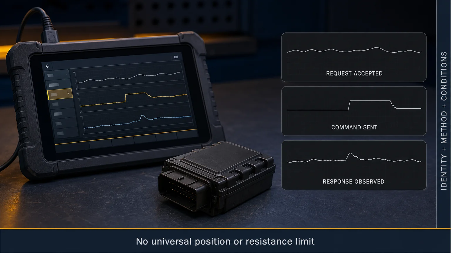
Command agreement does not automatically prove that the vane or wastegate mechanism moves freely under temperature and exhaust load. Command disagreement does not automatically condemn the actuator; low supply pressure, wiring resistance, connector damage, calibration, learned values, linkage binding and mechanical stops can create similar data. Use the turbo actuator symptoms guide when the control chain needs a deeper electrical-versus-mechanical boundary.
Commanded-versus-actual data is meaningful only when the parameter definitions, test state and linkage are known. This illustration is not an application-specific waveform.
After external checks, isolate and inspect the turbocharger using the applicable service method. Photograph identification plates and all connections before removal. Look for fresh compressor or turbine blade impact, housing contact, heavy contamination, cracked housings, abnormal deposits, loose fasteners, oil-feed or drain restriction and evidence that gaskets or sealant blocked a passage. Check shaft movement only by the manufacturer's method; dry hand feel is not a universal wear gauge, and specified radial movement can differ by bearing design and oil-film state.
Do not rotate, wash, dismantle or polish a claim unit before the evidence is recorded. Cleaning can remove foreign-object fragments, oil-carbon patterns and contact marks needed to distinguish root cause. A damaged turbo may require replacement, but the case still remains incomplete until the air, exhaust, lubrication and control causes that could damage the replacement are resolved.
When replacement is supported, match the complete assembly number and application—not only the visible housing. Verify inlet and outlet flanges, compressor connections, oil feed and drain, coolant ports, actuator type and connector, housing orientation, brackets and calibration requirements. Browse the heavy-duty turbocharger range as a reference path, then confirm the exact engine and removed-unit evidence before quotation.
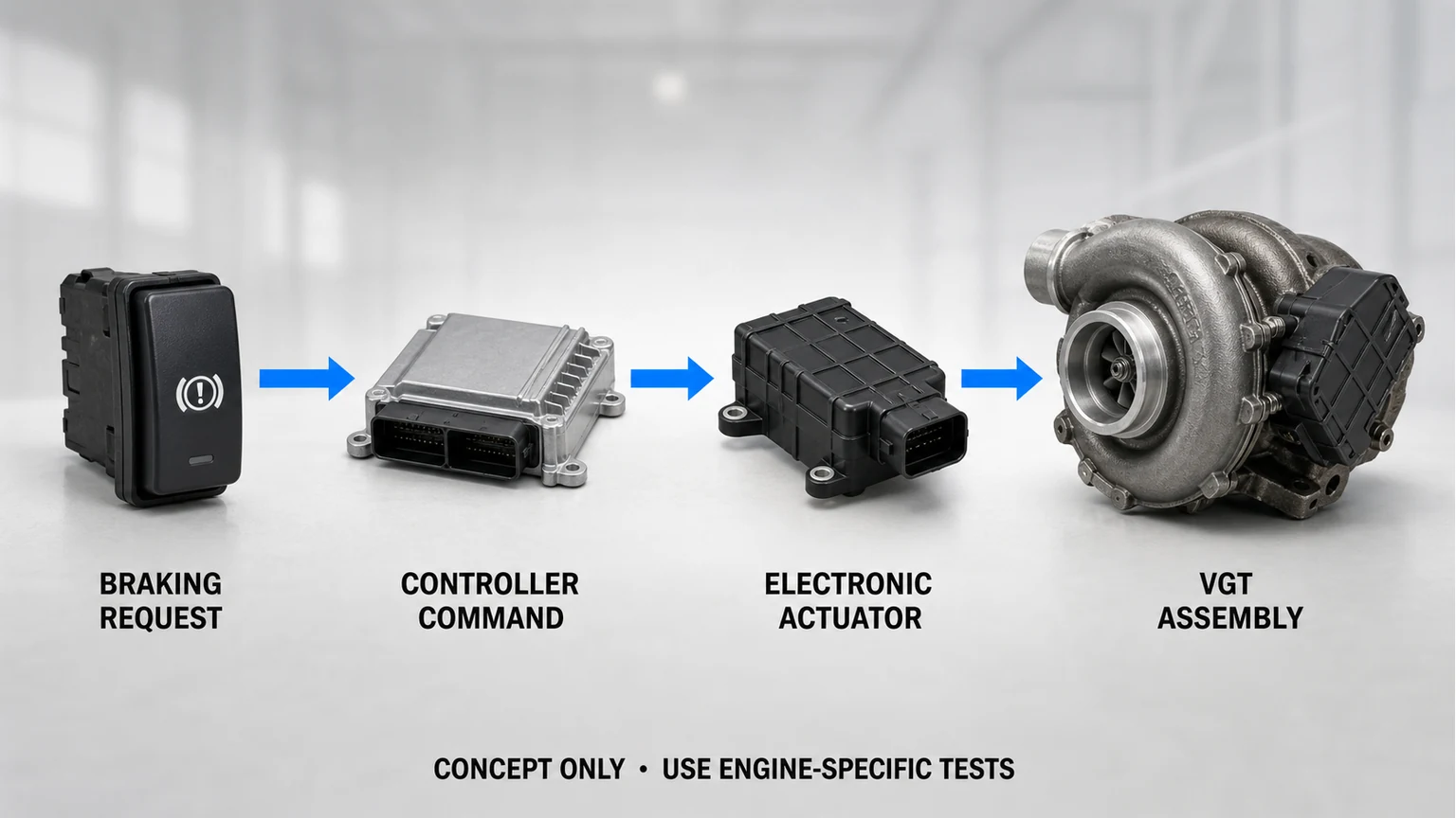
The same actuator and vane mechanism can participate in several control functions. Separate command, mechanism and exhaust response before assigning the underboost cause.
A useful distributor or warranty file allows someone who did not inspect the truck to follow the reasoning. Include the engine and vehicle identity, turbo assembly number, installation date and operating time, complaint and codes, maintenance and recent repair history, synchronized test data, air-path leak result, intake and exhaust findings, actuator command/actual evidence, lubrication findings, photographs before and after removal, and the final disposition. Label each file with the same case number.
State observations separately from conclusions. “Charge-air hose split at clamp; leak reproduced at the approved test condition” is evidence. “Turbo caused low boost” is a conclusion that requires additional support. If a required test was not available, mark it unavailable rather than inventing a pass. If the unit will be returned, cap every opening, retain loose evidence in a sealed identified bag and package the assembly so that shipping cannot add wheel or housing damage.
Stop and follow the engine maker's emergency or safety process when there is runaway risk, severe oil ingestion, wheel or housing breakup, fire damage, uncontrolled overspeed, unsafe exhaust temperature, major fuel leakage or another condition that makes loaded testing hazardous. Do not run a damaged turbo to obtain one more graph. The sequence also does not replace an application-specific service procedure, emissions rule, calibration process or warranty instruction.
No. It means the measured or inferred response did not meet the control system's expectation under the recorded condition. Intake restriction, charge-air leakage, exhaust problems, fueling, sensors, actuator control and turbo damage can all contribute. Reproduce the event and test the system in order.
Only within the method and pressure used. A joint can seal during a low-pressure static check yet open under heat, torque or higher pressure. Record the test condition and repeat the operating event after repair.
Not until power, ground, communication or pressure supply, linkage, stops, mechanism freedom and calibration requirements are checked. A lag identifies a control-chain problem; it does not identify the failed component by itself.
Send engine and vehicle identity, complete turbo number, all label and housing photographs, flange and connection views, actuator type and connector, oil and coolant interfaces, housing orientation, quantity, destination and the failure evidence that could affect installation.
It may temporarily change the symptom, but it does not remove the leak and can expose the replacement to excessive speed or thermal demand. Correct the verified system cause and validate the same load event.
When the test file supports replacement, send Elecdura the turbo identification and failure packet with required quantity and destination. The quotation should state the proposed aftermarket reference and unresolved matching fields. Keep the original evidence until the replacement has been installed and the complaint has been rechecked under the same controlled condition.
Technical references reviewed September 4, 2026: Garrett Motion Turbocharger System Diagnostics Guide; Garrett Motion Turbocharger Installation Rules; BorgWarner Turbocharger Diagnostic Matrix; BorgWarner Turbocharger Troubleshooting. Manufacturer guidance is applied only to the systems it covers; engine-specific service information governs limits and procedures.