ELECDURA NETWORK

Your Whole New Supply Chain For Heavy-Duty Parts
Whatsapp:
+86 18915027366
Phone:
+86 18915027366
Views: 0 Author: Site Editor Publish Time: 2026-07-20 Origin: Site
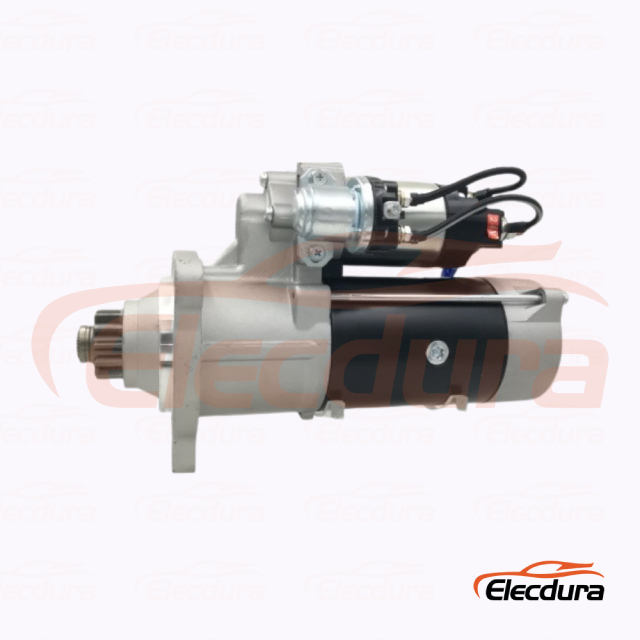
The 39MT name identifies a heavy-duty gear-reduction starter family, not one universal starter. Units within that family can differ in system voltage, power, rotation, pinion tooth count, nose and mount geometry, solenoid position, terminal arrangement, protection, and application approval. Ordering from the family name alone can produce a starter that looks familiar but cannot engage the flywheel or connect safely.
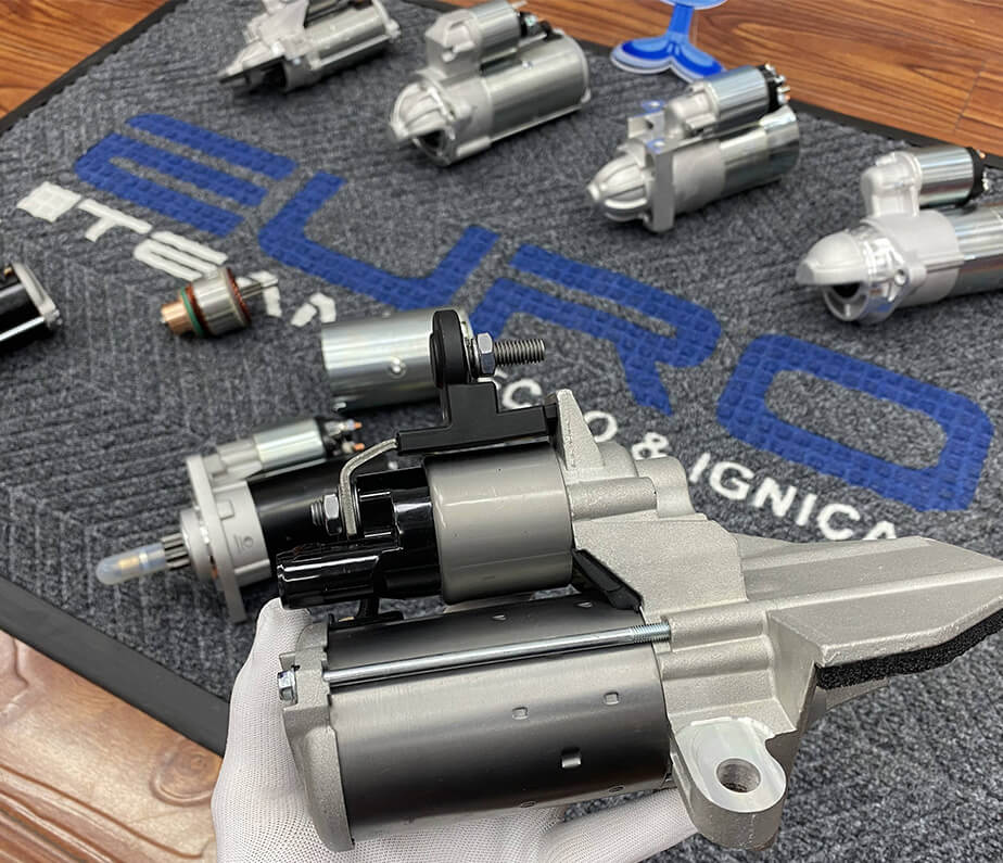
Elecdurauto provides a heavy-duty starter motor catalog for trucks, diesel engines, buses, construction equipment, agricultural machinery, and other severe-duty applications. References are used for technical matching. Unless product origin is verified, the accurate description is an OE-grade aftermarket replacement, aftermarket equivalent, or starter for OE-number matching.
This guide organizes 39MT selection around evidence. It helps distributors, importers, rebuilders, fleet workshops, and repair businesses convert an old unit, vehicle record, or buyer inquiry into a controlled fitment specification before a sample or bulk order is approved.
Use the most specific evidence first. The old starter label and stamped numbers usually outrank a buyer's remembered model-family name. Add engine model, vehicle make, build date, chassis information, system voltage, and clear photographs. If records conflict, hold the order until the electrical and mechanical interfaces are measured.
Complete old-unit label, stamped reference, and any service tag.
Vehicle, engine, equipment model, build date, and system voltage.
Mounting flange, register, bolt pattern, and nose geometry.
Pinion teeth, pitch, diameter, rotation, and resting position.
Solenoid clocking, battery stud, control terminal, and cable route.
Catalog cross-references, repair records, supplier databases, and online model-family pages are useful confirmation. They should support the physical evidence rather than replace it. A cross-reference may span revisions or application variants that require different connectors or pinions.
A real 39MT example shows why voltage, power, tooth count, rotation, and mounting must be read together.
Voltage is a hard boundary. A 12V starter and a 24V starter may share case architecture, yet their windings, solenoid, current behavior, and vehicle battery configuration are different. Never infer voltage from the number of batteries because banks can be wired in series, parallel, or switched arrangements.
Read the electrical diagram or label, inspect battery interconnections, and measure the system using the approved procedure. Photograph the old starter label and record solenoid markings. If a vehicle has a series-parallel switch or special start circuit, document how start voltage is created.
The 10461758-reference 24V 39MT starter is listed with a 24V, 8.5kW, 12-tooth direction for Cummins 5.9 ISB-related applications. The 19011506-reference 12V 39MT starter is a 12V example. These listings illustrate why a family-level keyword cannot determine the electrical specification.
Changing battery connections or installing a different solenoid is not an acceptable substitute for an approved starter specification. It can damage the starter, cables, batteries, controls, and flywheel while creating a fire risk.
Rated power should be evaluated with engine displacement, compression, oil viscosity, ambient temperature, cranking-speed requirement, start frequency, and expected cable voltage. More power is not automatically safer if the pinion, mount, ring gear, batteries, cables, or switchgear are not approved for the configuration.
Mining, construction, agriculture, and winter fleets may need stronger cold-start margin because oil viscosity, battery output, and engine friction change with temperature. Record the lowest expected start temperature, battery type, cable length, and any intake or coolant heating strategy.
Refuse, delivery, bus, and vocational applications may cycle the starter more often than highway tractors. Duty-cycle selection should consider thermal recovery between starts, solenoid contact life, drive engagement, brush wear, and fleet rules for repeated cranking attempts.
The drive must move into the ring gear at the correct depth and mesh. Tooth count alone is incomplete. Pinion pitch, outside diameter, pressure geometry, rotation, chamfer, rest position, overhang, and travel all affect engagement. A mismatch can cause grinding, tip contact, slow cranking, drive breakage, or ring-gear damage.
Count teeth, measure diameter with an appropriate tool, photograph the tooth form, record drive position, and inspect wear. Rotate the engine according to service procedure to examine more than one ring-gear section when damage is suspected.
Rounded leading edges can reflect repeated partial engagement. Burrs, chips, and bright impact marks may indicate incorrect spacing, damaged ring-gear teeth, low solenoid force, low voltage, or engine kickback. Correct the cause before installing a new starter.
A starter can have the right pinion and still fail to fit the housing. Compare the mounting flange, register diameter, bolt-hole pattern, fastener size, nose length, locating surfaces, and support bracket. The register usually establishes alignment; bolts alone should not force a misaligned starter into place.
Record the solenoid position relative to the mounting holes. Check clearance to the engine block, frame, exhaust, aftertreatment, hoses, and shields. Verify that battery and control cables can reach without tension, crossing heat sources, or contacting moving parts.
Close interface inspection prevents a familiar starter family from hiding a mounting or terminal mismatch.
Heavy starters may use a rear support, shield, or cable bracket to control vibration and temperature. Missing hardware changes the loading on the nose, housing, and terminals. Include it in the receiving and installation check.
Rotation is viewed from a defined end, so the description must state the viewpoint. Confirm with the old unit, service information, or approved supplier data. A wrong-rotation starter cannot be corrected by swapping battery cables and should never be energized for an improvised test.
Verify stud diameter, thread, insulation, clearance, and required cable-stack order. Cables must not twist the studs. Compare the old and replacement terminals before installation and use the specified torque and protective boots.
Identify the start-signal terminal, connector lock, polarity requirements, and any auxiliary or monitoring circuit. A connector that fits physically may use a different internal function. Confirm control voltage under load so a vehicle-side loss is not blamed on the starter.
Once a sample passes, preserve the evidence as a controlled application file. Include old and approved labels, photos from consistent angles, dimensions, pinion data, voltage, power, rotation, clocking, terminal layout, packaging, test results, and vehicle acceptance. Assign a fleet or customer reference that links the file to purchasing records.
Require notification before changes to windings, drive, solenoid, housing, supplier subcomponents, connectors, labels, or packaging. A revised product may still fit, but it must be reviewed against the approved evidence rather than entering the fleet as an unnoticed substitution.
The same fleet model can contain different engines, transmissions, flywheel housings, or electrical systems across build years. Record exceptions by VIN or build range and train buyers not to collapse them into one 39MT line.
Place the old and proposed 39MT units on a clean bench in the same orientation. Compare each interface systematically and photograph the result. This gate catches errors before the vehicle is disabled and prevents the installer from forcing a near-match into service. It is especially valuable when the supplier or buyer uses a superseding reference.
Use the mounting face and register as datums. Measure bolt pattern, nose projection, pinion rest position, pinion diameter and tooth count, and case clearance from those references. Record the tool and tolerance. Measurements taken from arbitrary housing edges are difficult to repeat and can hide a meaningful offset.
Install temporary templates or use photographs to confirm that battery lugs, control connectors, boots, and support clamps clear the engine and frame. Check the tool access required for correct terminal torque. A terminal that technically fits but cannot be tightened or insulated safely is not an acceptable match.
Require a technician or inspector to sign the comparison record before the old core leaves the site. The sign-off should identify differences and their approved resolution. This simple control protects the evidence needed if the replacement later shows engagement or installation problems.
Returns do not begin only at installation. A correct starter can be damaged, mislabeled, or mixed during storage and transport. For wholesale supply, connect the carton label, unit label, purchase order, reference, voltage, and batch. Use protective packaging that prevents the heavy unit from moving and protects the pinion, nose, terminals, and connector.
Place voltage and rotation information where receiving and warehouse teams can see it without opening technical documents. Use a controlled label format and verify it against the unit during packing. A clear label does not replace inspection, but it reduces mixed-stock selection errors.
Use caps or guards for threaded studs and connectors, support the starter so the nose does not carry impact, and control moisture. Inspect packaging after transit testing or representative shipment. Reused cartons should not lose structural strength or carry obsolete labels.
Record serial or lot information on dispatch documents. When a customer reports a problem, request vehicle evidence, installation measurements, cranking readings, and the unit label. Traceability lets the supplier separate an individual handling event from a repeated batch or specification issue.
For repeat wholesale orders, retain one approved carton and label specification with the technical file. Receiving teams can then detect a mixed voltage, changed connector, or altered product identity before warehouse stock is allocated to customer orders.
Warehouse accuracy is part of fitment control.
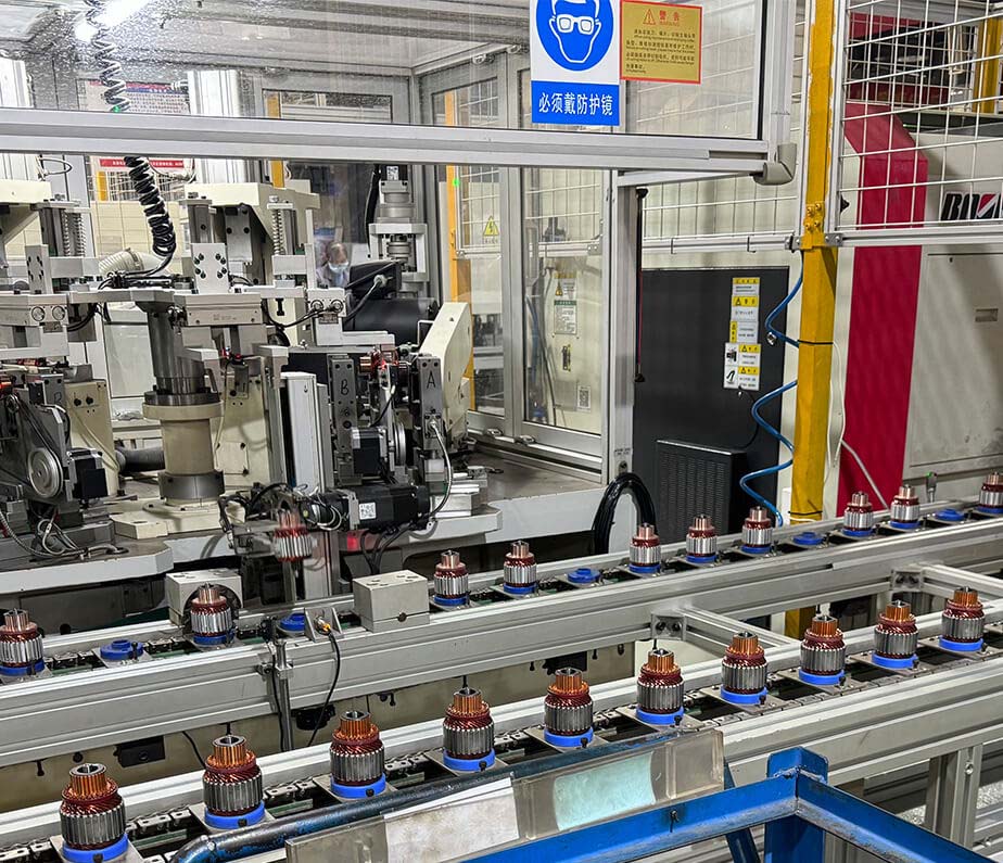
A polished housing is not enough. Review incoming component control, armature and field construction, drive and solenoid consistency, insulation, assembly torque, test capability, labeling, and traceability. The Elecdurauto production and quality approach gives buyers context for evaluating how aftermarket products are controlled.
No-load speed and current at defined voltage and temperature.
Solenoid pull-in, hold, contact voltage drop, and release.
Loaded torque or performance on an approved fixture.
Insulation, abnormal noise, drive travel, and pinion return.
Dimensional comparison with the approved sample.
Controlled assembly and retained test data help keep repeat 39MT orders consistent.
Inspect carton labels, unit labels, references, voltage, power, pinion, mount, clocking, terminals, finish, damage, and packaging. Use a sampling plan tied to risk and retain photographs by lot. Quarantine unapproved changes before units are distributed.
After installation, confirm battery condition, cable routing, terminal torque, ground integrity, clearance, and support hardware. Measure cranking voltage at the batteries and starter, positive and negative voltage drop, cranking speed, and current where approved. Listen for engagement and release through several controlled starts.
Grinding, delayed engagement, a drive that remains engaged, cable heat, excessive voltage drop, abnormal solenoid chatter, slow cranking, smoke, or inconsistent release requires shutdown and investigation. Do not continue repeated starts to see whether a mechanical mismatch improves.
Attach the vehicle test to the application approval file. Note installation date, mileage or hours, starter batch, battery result, cable corrections, and any ring-gear observations. That record becomes the baseline for warranty and future sourcing.
A correct 39MT selection is the intersection of electrical system, engine duty, pinion interface, mounting geometry, rotation, clocking, terminals, application evidence, and test control. The family name narrows the search; it does not complete it.
Importers, distributors, and fleet buyers can submit a 39MT matching request with the label, engine and vehicle details, system voltage, mount and pinion measurements, connector photos, quantity, and required tests. Complete evidence supports a reliable aftermarket match and reduces returns caused by family-level assumptions.