ELECDURA NETWORK

Your Whole New Supply Chain For Heavy-Duty Parts
Whatsapp:
+86 18915027366
Phone:
+86 18915027366
Views: 0 Author: Site Editor Publish Time: 2026-09-01 Origin: Site
An injector-circuit-open code does not identify the injector as the failed part. It identifies an electrical path that the controller could not operate or monitor as expected under defined conditions. The open may be at a terminal, connector, short sub-harness, engine harness, injector winding, or—less commonly—inside the driver or controller path. Freeze the exact code, engine and control-system identity before disconnecting anything. Then inspect and test the circuit with the applicable service procedure. Order an injector only if the evidence reaches the injector; order a harness or connector only if the fault follows that repair boundary.
This diagnostic handoff is for fleet workshops and distributors deciding whether a complaint belongs in the heavy-duty diesel injector category or in an electrical repair. It does not publish a universal resistance, test voltage or pin assignment.
Record the full diagnostic trouble code, occurrence count or history state where available, engine serial and configuration, operating conditions, affected cylinder or circuit, and every related supply or communication code. “Injector open” copied from a generic scanner is not enough. A manufacturer tool may distinguish a low-side, high-side, shared supply or cylinder-specific path, and that distinction changes the isolation plan.
Do not clear codes, swap injectors or flex the harness before retaining the original state. An intermittent terminal contact can disappear during handling. A code that returns only with heat, vibration or a particular engine state requires those conditions to be documented rather than replaced by an uncontrolled wiggle test.
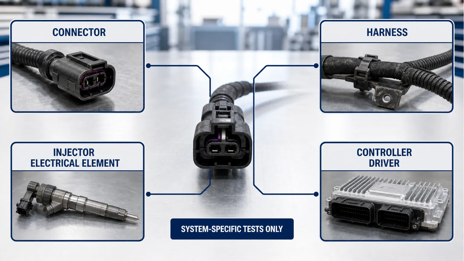
Possible boundary | Evidence that can support it | What still needs separation |
|---|---|---|
Connector or terminal | Specified terminal inspection, retention or contact evidence | Damage caused by handling versus the original fault |
Harness segment | Continuity, isolation or voltage-drop result using the approved circuit state | Shared supply, splice and driver-side effects |
Injector electrical element | System-appropriate resistance, inductance or insulation result | Hydraulic performance and calibration |
Driver or controller path | All external paths verified plus the manufacturer's directed driver test | Power, ground, software and connector prerequisites |
The branches are evidence boundaries, not a sequence for applying power to an injector.
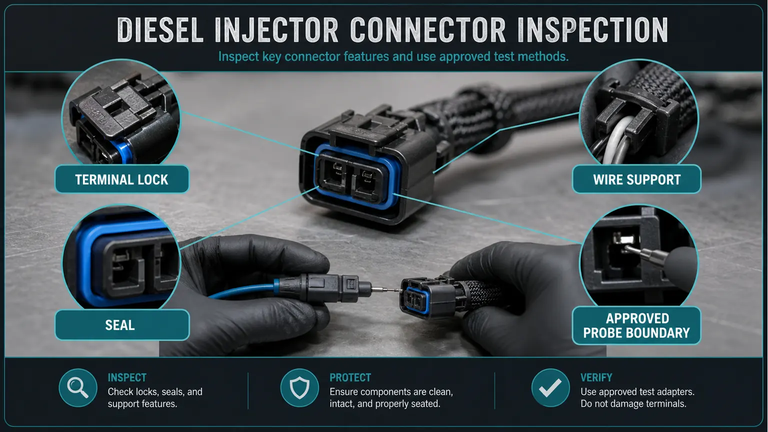
Disconnect only as the service procedure permits. Examine locks, seals, backshell support, moisture, fretting, spread or backed-out terminals, insulation strain and routing near heat or moving hardware. Use the specified terminal probe or test adapter; forcing a generic meter lead into a terminal can change its contact force and invalidate the evidence.
GM bulletin 23-NA-027 is a useful narrow example. It addresses defined L5P and L5D applications and directs technicians to inspect specified injector-connector terminals and follow GM wiring-repair and routing information. It is not authority to apply its terminal treatment, probe, repair or vehicle coverage to every heavy-duty diesel system. The correct lesson is to preserve the bulletin's application boundary.
Use the wiring diagram to identify shared supplies, splices, pass-through connectors, under-cover harness sections and controller-side terminals. Test the smallest section that can distinguish the competing causes. A continuity result with the circuit unloaded may miss a contact that opens under vibration or temperature; a load or voltage-drop method must still be the one authorized for that circuit.
Keep the controller and injector protected from improvised external power. Some common-rail injectors use drive strategies and voltages that are not represented by battery voltage. Back-probing the wrong terminal can damage a driver, distort a waveform or create a safety hazard. If the procedure requires a breakout lead, current clamp, oscilloscope or dedicated injector tester, record the tool and connection rather than substituting a universal shortcut.
A same-engine companion circuit can help reveal whether one channel behaves differently, but the comparison does not erase cylinder identity, shared circuits or different operating commands. Swapping connectors or injectors merely to see whether the code moves can create fuel, calibration, sealing and traceability problems. Follow the manufacturer isolation sequence instead.
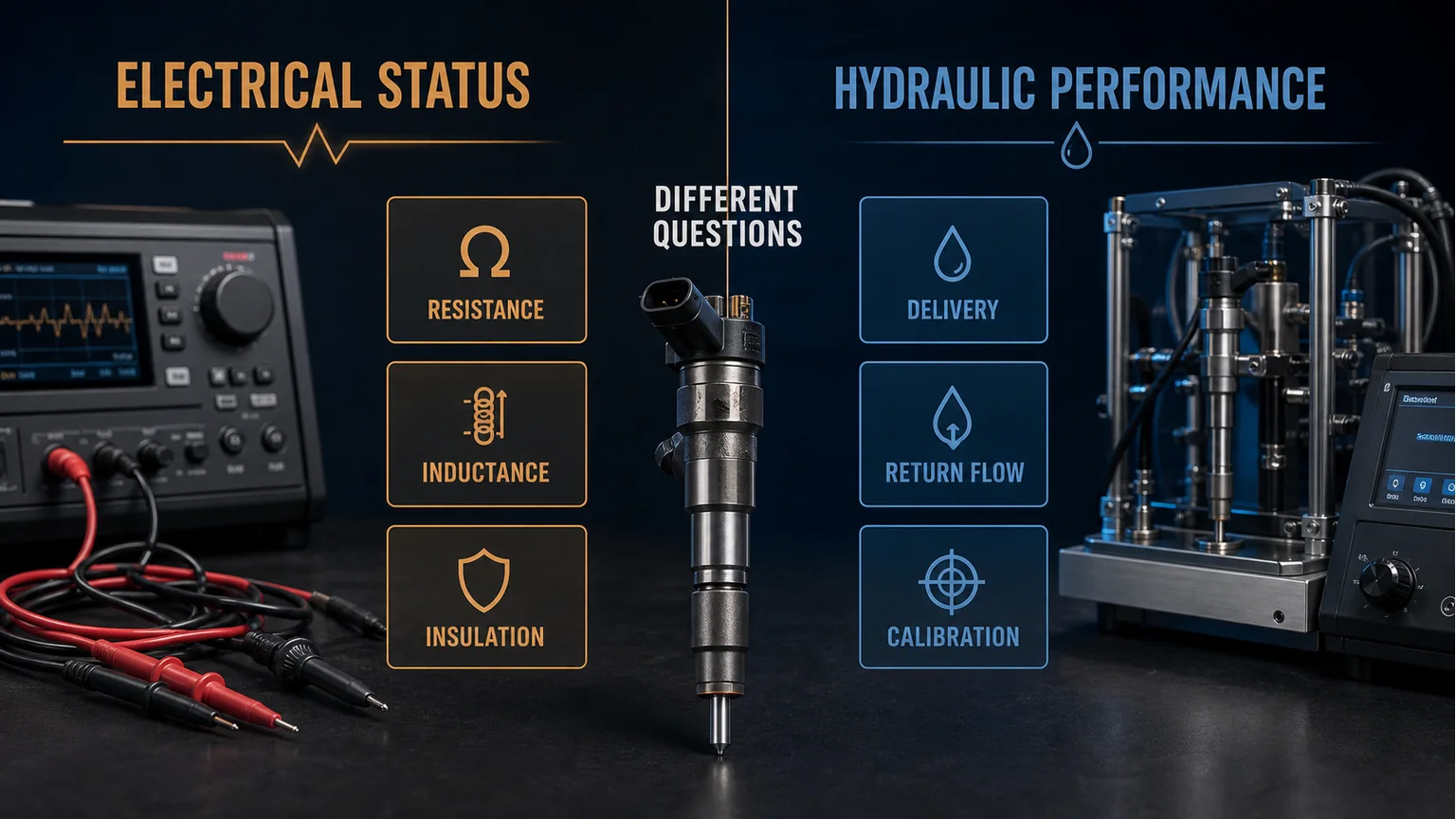
Delphi describes common-rail injector electrical evaluation with equipment capable of appropriate resistance, inductance and insulation checks. Those measurements answer defined electrical questions. They do not prove nozzle sealing, return flow, delivery quantity, spray quality or calibration. Conversely, a hydraulic imbalance does not prove that an electrical-open code belongs to the injector winding.
A buyer should receive the failed electrical test and the exact injector identity, not a statement that the injector “tested bad” with no method or limit.
Approve a terminal repair when the specified contact defect is confirmed and the remaining circuit passes the required checks. Approve a harness segment when its failed path is isolated and routing or environmental cause is addressed. Approve an injector when its electrical element fails the applicable test or when independent hydraulic evidence supports replacement. Escalate a possible driver fault only after power, ground, external wiring, connectors and required prerequisites are verified.
After repair, reassemble with the correct locks, seals, routing and support. Repeat the original diagnostic monitor or test under comparable conditions and retain the result. A code that happens not to return during a short idle is weaker evidence than the manufacturer's verification procedure.
This article does not authorize testing a piezoelectric or solenoid injector with an ordinary battery, bypassing a controller, opening a high-pressure fuel system without its depressurization procedure, or probing an unspecified terminal. It also does not cover an engine whose code description, wiring revision or injector system has not been identified.
If fuel leakage, damaged high-pressure lines, overheating wiring or uncontrolled engine operation is present, follow the applicable shutdown and safety process before gathering additional data.
For a harness or connector request, include the engine identity, circuit and connector location, terminal count, locking and seal details, branch lengths, mounting clips, photographs and the test that isolated the damaged section. For an injector request, include the engine identity, complete removed-unit number, cylinder record, electrical and hydraulic evidence, calibration or coding requirements, quantity and destination.
If the evidence supports an injector, send Elecdura the injector identity and diagnostic record for matching and quotation. A proposed match does not certify the controller, harness or original diagnosis.
It narrows the affected channel, but that channel still includes its terminals, wiring and injector element. Use the manufacturer's isolation points to determine whether the open remains on the harness side or reaches the injector. The result supports an injector order only when the injector boundary fails; cylinder-specific wording alone is not that proof.
Yes. A defined resistance, inductance or insulation result can show that the tested electrical property is within its limit, but it does not measure leakage, delivery, return flow, atomization or calibration. If the complaint is hydraulic, preserve the electrical pass and continue with the appropriate fuel-system test instead of reinterpreting it as a complete injector certification.
Only when the application permits that repair, the specified terminals, seals and tooling are used, wire length and routing remain compliant, and the completed circuit passes the required verification. A generic pigtail that physically plugs in may have different terminal plating, wire size, sealing or strain relief. Record the repair source so repeat failures can be traced.
Not by itself. Simultaneous replacement destroys the ability to identify which boundary failed and can hide a routing or driver problem. Capture the conditions, use section-by-section tests and change one justified boundary at a time unless the manufacturer procedure or confirmed physical damage requires a combined repair.
Retain the complete injector identity, engine and cylinder record, exact codes, the applicable electrical method and limits, measured result, connector and harness checks, installation history and requested return handling. Do not dismantle or clean the unit before instructions are received. The evidence supports review but does not override the actual warranty terms.