ELECDURA NETWORK

Your Whole New Supply Chain For Heavy-Duty Parts
Whatsapp:
+86 18915027366
Phone:
+86 18915027366

25/105100
25/105100
OE-Equivalent Replacement Quality
IATF 16949 / ISO 9001 / CE / RoHS
50 pcs
7 - 15 Days
12 Months
25/105100
JCB 3CX and 4CX transmission or hydraulic control using 25/105100
Confirm 12v, connector, 3/4-20 unf-2a, seals and hydraulic circuit before installation.
| Quantity: | |
|---|---|
25/105100 is a 12V hydraulic solenoid valve for JCB 3CX and 4CX transmission or hydraulic control using 25/105100. Buyers should confirm the complete old marking, electrical version, connector, 3/4-20 unf-2a and hydraulic function before approving replacement stock.
Specification | Value |
|---|---|
Product Type | Hydraulic Solenoid Valve |
Primary Reference | 25/105100 |
Cross References | 25/105100 |
Electrical Version | 12V |
Working Pressure Reference | 350 bar |
Interface | 3/4-20 UNF-2A |
Application Scope | JCB 3CX and 4CX transmission or hydraulic control using 25/105100 |
MOQ | 50 pcs |
Delivery Time | 7 to 15 Days |
Warranty | 12 Months |
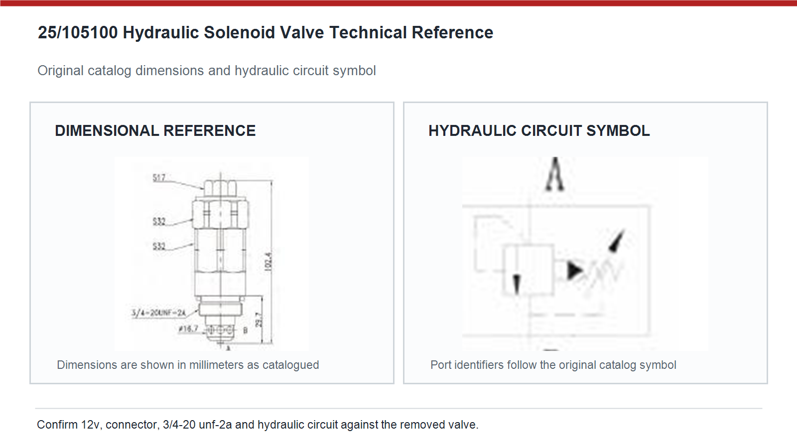
Use the original catalog dimensional reference and hydraulic symbol to compare the valve with the removed component and the machine schematic before purchase approval.
Complete every control point below before a sample or bulk order is released.
Approval Point | Buyer Review |
|---|---|
Reference | 25/105100 |
Electrical | 12V; verify at the loaded connector during the actual command |
Mechanical | Compare 3/4-20 unf-2a, cartridge length, seals and installed clearance |
Hydraulic | Confirm normal state, energized state and manifold port relationship |
Machine Evidence | JCB 3CX and 4CX transmission or hydraulic control using 25/105100 |
Separate electrical command, cartridge movement and machine response so the actual wiring or hydraulic fault is not hidden by a parts replacement.
Observed Condition | Recommended Check |
|---|---|
No movement | Check loaded connector voltage, ground, controller command and coil resistance. |
Slow response | Inspect oil cleanliness, filter condition, viscosity and cartridge movement. |
Reversed response | Stop operation and compare normal and energized port logic with the original valve. |
External leakage | Inspect seals, cartridge surface, manifold bore and correct seating depth. |
Repeated heating | Confirm voltage, duty cycle, connector resistance and full magnetic movement. |
During a pump control fault appears only under load, keep the verified reference, measurements and test result in the service record. Approve 25/105100 from the complete old valve marking, 12v electrical version, connector keying, 3/4-20 unf-2a, sealing lands and normal hydraulic state. A shared equipment model does not prove interchangeability because pump and manifold revisions can change during production. Send the machine model, serial number and clear removed part photos with the inquiry.
During a seal leakage complaint is assessed, keep the verified reference, measurements and test result in the service record. Read the coil label first and measure voltage at the connector while the real machine command is active. The working reference for this page is 12V. Do not infer voltage only from battery count because converters, harness changes and mixed voltage fleets can create misleading assumptions. Record the verified value on the purchase order and incoming inspection label.
During a replacement warranty claim is reviewed, keep the verified reference, measurements and test result in the service record. Measure supply and ground at the loaded connector, then check coil resistance and verify that the controller is actually issuing the command. If electrical input is correct, inspect oil cleanliness, filter condition, cartridge movement and manifold contamination. Separate electrical command from hydraulic response before replacing another valve, otherwise a harness or blocked pilot passage may be missed.
During a maintenance planner builds critical spare stock, keep the verified reference, measurements and test result in the service record. Use the drawing to compare overall length, thread or flange position, sealing diameters and connector clearance with the removed component. Read the spring side of the hydraulic symbol as the normal state and the solenoid side as the energized state. Port letters are catalog identifiers and must be reconciled with the equipment schematic before commissioning.
During a hydraulic manifold is rebuilt, keep the verified reference, measurements and test result in the service record. Verify commanded voltage under load, coil duty cycle, connector resistance and whether the hydraulic element reaches its intended position. Low voltage can prevent full magnetic pull, while excessive voltage or continuous energization can overheat the winding. Contamination that restricts cartridge movement can also increase operating stress, so correct the electrical or hydraulic root cause before fitting another coil.
During a dealer parts counter checks an old sample, keep the verified reference, measurements and test result in the service record. Check the printed reference and voltage against the purchase order, then sample connector keying, overall length, mounting interface, seal count and coil resistance. Keep voltage or suffix variants physically separated and traceable. For the first production lot, compare one unit with the approved old component before releasing the remaining quantity to warehouse stock or field service.
During a repeat coil heating case is investigated, keep the verified reference, measurements and test result in the service record. A controlled sample review should confirm physical fit, connector engagement, coil current, leakage and the machine response in both normal and energized states. For this hydraulic solenoid valve, record warm oil behavior and response time as well as cold start operation. Retain the approved label photos and measurements so the production lot can be checked against the same acceptance record.
Send the complete old valve marking, confirmed voltage, machine model and serial number, connector photos, interface dimensions and required quantity for a fitment focused B2B quotation.