Your Whole New Supply Chain For Heavy-Duty Parts
Whatsapp:
+86 18915027366
Phone:
+86 18915027366
Views: 0 Author: Site Editor Publish Time: 2026-09-01 Origin: Site
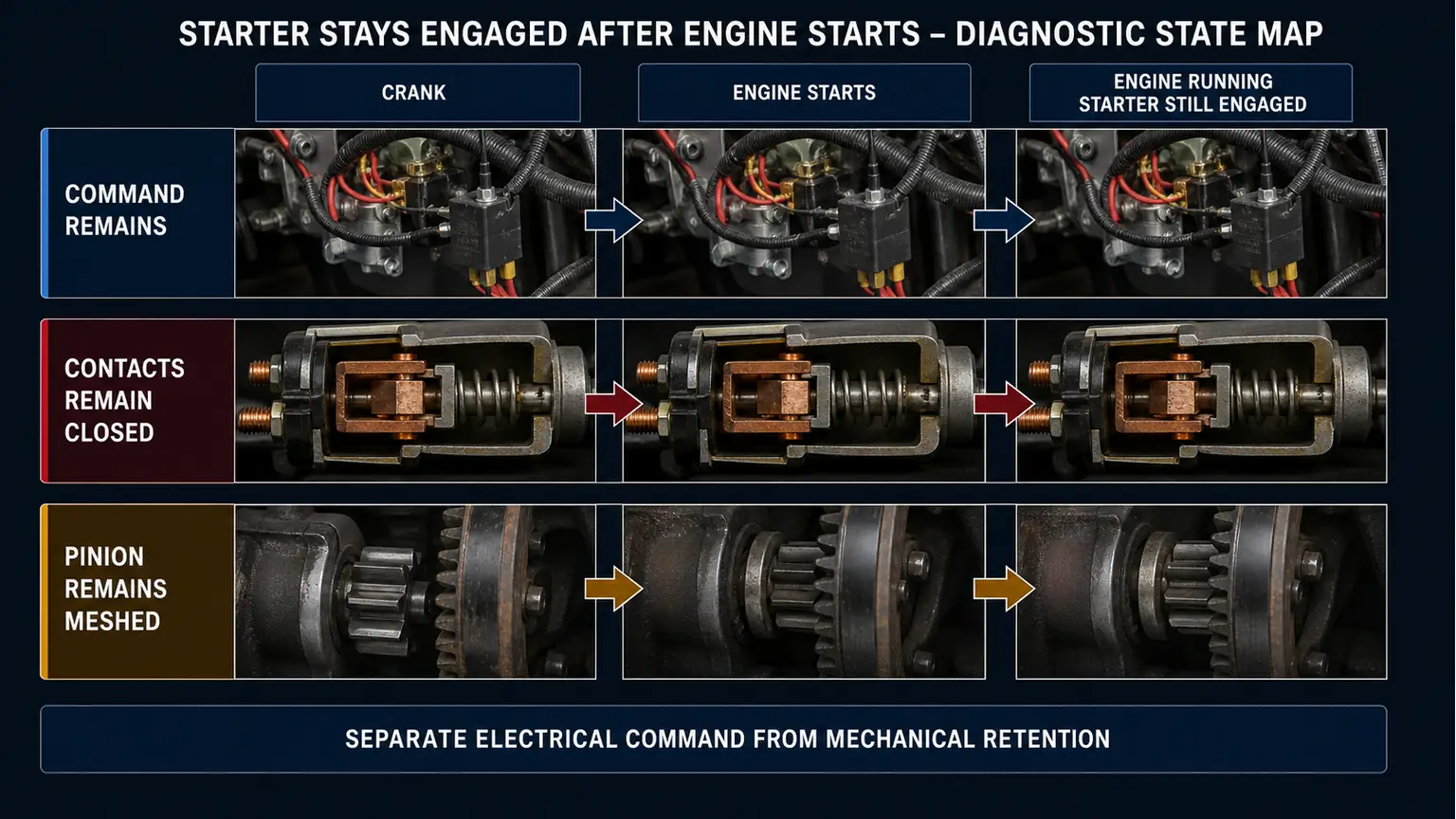
If a starter remains engaged after the engine starts, stop the test and isolate the vehicle by its approved safety procedure. The engine can drive the starter at destructive speed. Before ordering parts, determine which of three states persisted after the start request should have ended: command voltage remained at the starter control terminal, the high-current contacts remained closed after command disappeared, or the motor stopped but the pinion stayed mechanically engaged. These boundaries point to different repairs. Replacing the starter without checking the start circuit, mounting and ring gear can destroy the replacement and weaken a warranty investigation.
This article is for fleet workshops and buyers separating a system fault from a heavy-duty starter motor request. It is distinct from an overrunning clutch that slips while cranking.
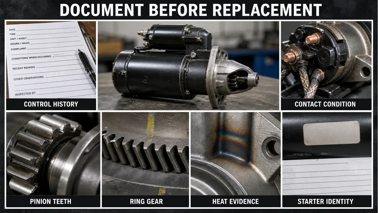
Record whether the starter motor continued to run, the pinion remained meshed, or both occurred. Note when the key or start request was released, warning messages, engine speed, sound, duration and how the event ended. Photograph heat discoloration, smoke, cable or relay damage only after the system is safe. Do not repeat the event to obtain a better recording.
Inspect the starter model, mounting orientation, pinion and ring-gear application, wiring, remote relay or integrated magnetic switch, and any recent engine, flywheel, transmission or start-circuit work. A wrong pinion position or control-wire change after an engine swap can produce a different failure path from welded contacts inside a correctly matched starter.
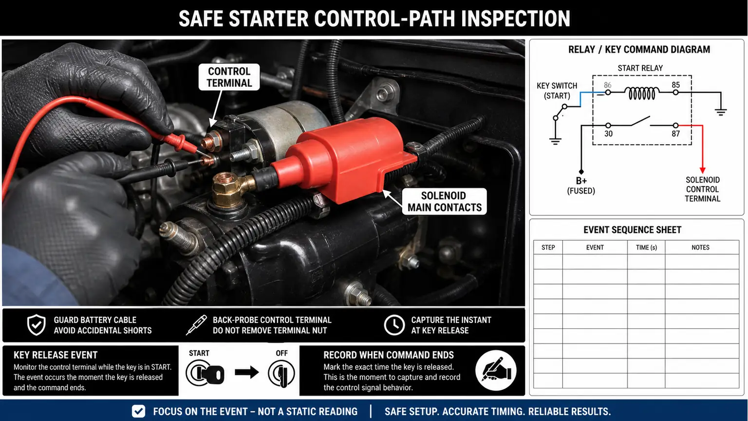
Use the vehicle wiring diagram to identify the starter control terminal and every element that can maintain it: key or start switch, relay, control module, interlock, remote-start device and wiring. With the vehicle secured and the engine prevented from starting as the service procedure requires, measure the control state using the specified test point and method. Do not assume terminal names or safe access from another starter family.
If the command remains after release, the starter may be obeying the vehicle. Trace the circuit upstream and inspect for a sticking switch or relay, backfeed, wiring error or module command according to the application. Bosch notes that excessively long terminal-50 actuation can discolor solenoid-switch winding insulation and contribute to non-disengagement; the external command must be checked rather than treating the heat damage as automatic proof of an originally defective starter.
If the control command ends but the starter motor continues to receive high current, the contactor or solenoid-switch boundary requires investigation. Preserve the cable and relay state; do not strike the unit, bridge terminals or repeatedly disconnect a live high-current path as an improvised diagnostic. Follow the vehicle procedure to isolate power safely.
Welded or mechanically stuck contacts may result from internal wear, excessive actuation time, low-voltage contact chatter, a control problem or previous damage. The part can be damaged and still not be the original root cause. Record battery and cable condition, start-command duration and circuit evidence before authorizing a starter, magnetic switch or solenoid repair.
If electrical power is removed and the motor stops but the pinion remains against the ring gear, inspect the mechanical return path, lever and spring condition, helical movement, mounting alignment, pinion position and ring gear by the applicable service procedure. Do not pry an installed pinion free to prove the starter is defective; that can alter the evidence and damage the teeth.
Bosch's non-disengaging-starter technical note illustrates blue or scorched parts, damaged winding insulation and severe overspeed damage. These observations can confirm that the starter was driven too long, but some destructive inspection may prevent the manufacturer from assessing a return. Photograph the exterior and obtain return instructions before opening the starter or solenoid housing.
Delco Remy warranty guidance also treats a milled pinion as evidence of engagement with a rotating ring gear and points to possible external control-circuit causes. Therefore, inspect both the starter and the ring gear. Installing a new unit against damaged teeth or an unresolved command can create the same failure again.
Observed after release | Primary investigation | Parts decision held until |
|---|---|---|
Control command remains | Switch, relay, module, interlock and wiring path | Upstream source and starter damage are both known |
Command ends; motor remains powered | High-current contact or magnetic-switch state | Cause, cable condition and safe de-energization are documented |
Motor stops; pinion remains meshed | Drive return, mounting, pinion position and ring gear | Mechanical fit and tooth condition are verified |
More than one boundary can be damaged. The purpose of the table is to preserve sequence, not force a single-component answer.
This is not an instruction to test an engaged starter with the engine running, bypass a neutral or clutch interlock, bridge high-current terminals, repeat an overspeed event or disconnect a battery under uncontrolled load. It also does not apply when the sound was a brief normal overrun that has not been identified as continued motor power or pinion engagement.
If smoke, cable heating, fire risk, uncontrolled cranking or unsafe vehicle movement is present, follow the emergency isolation procedure before diagnosis.
A starter request needs the complete removed-unit label, voltage, power and tooth information where verified, rotation, mounting, pinion-at-rest measurements required by the catalog, terminal and remote-switch arrangement, engine and flywheel application, and photographs of pinion and ring gear. A relay or control repair needs the wiring identity and test that isolated the upstream source.
The starter overrunning-clutch and kickback guide addresses a different torque-transfer complaint. When the complete-starter boundary is confirmed, send Elecdura the identity and failure record for matching and quotation.
It can change one control path, but the meaning depends on circuit design and when the observation was made. An integrated switch, welded high-current contact, backfeed or another relay path may remain. Use the wiring diagram and verify the starter control-terminal state; do not turn relay removal into a universal live test.
No. Milled or overheated teeth show harmful engagement with a rotating ring gear, but the cause may be prolonged electrical command, wrong pinion position, mounting error, ring-gear damage or a drive-return fault. Inspect the system chronology before deciding whether the starter, controls, mounting or flywheel boundary requires repair.
Low voltage can contribute to incomplete solenoid operation, contact chatter, heating and damage, but the complaint still requires circuit evidence. Test the battery bank and voltage-drop paths by the heavy-duty starting-system procedure, then examine command and contact release. A low reading does not prove every non-disengagement event has the same cause.
Only under the authorized return or service procedure and with the correct guarded equipment. An overspeed-damaged unit can be unsafe, and an unloaded bench spin may not reproduce mounting or ring-gear conditions. Preserve the external evidence first and ask whether disassembly or bench operation would compromise the claim.
Document that the start command releases correctly, high-current contacts open, battery and cable conditions meet the procedure, mounting and pinion position match the application, ring-gear teeth are acceptable, and any recent wiring change is corrected. Then verify one controlled start. Replacing only the visible damaged unit does not close those causes.