
English


KWE5K-20/G24D04-T
KWE5K-20/G24D04-T
OE-Equivalent Replacement Quality
IATF 16949 / ISO 9001 / CE / RoHS
50 pcs
7 - 15 Days
12 Months
KWE5K-20/G24D04-T
Kato HD820 hydraulic pump control using the complete KWE5K-20/G24D04-T marking
Confirm 24v, connector, threaded cartridge with lead connector, seals and hydraulic circuit before installation.
| Quantity: | |
|---|---|


KWE5K-20/G24D04-T is a hydraulic pump solenoid valve for Kato HD820 hydraulic pump control using the complete KWE5K-20/G24D04-T marking. Buyers should confirm the full reference, 24v, lead connector, threaded cartridge with lead connector before approving replacement stock.
Specification |
Confirmed Information |
|---|---|
Product Type |
Hydraulic Pump Solenoid Valve |
Primary Reference |
KWE5K-20/G24D04-T |
Cross References |
KWE5K-20/G24D04-T |
Electrical Version |
24V |
Working Pressure Reference |
240 bar catalog reference |
Interface |
Threaded cartridge with lead connector |
Application Scope |
Kato HD820 hydraulic pump control using the complete KWE5K-20/G24D04-T marking |
MOQ |
50 pcs |
Delivery Time |
7 to 15 Days |
Warranty |
12 Months |
Use the original catalog dimensional reference and hydraulic symbol to compare the valve with the removed component and machine schematic before purchase approval.
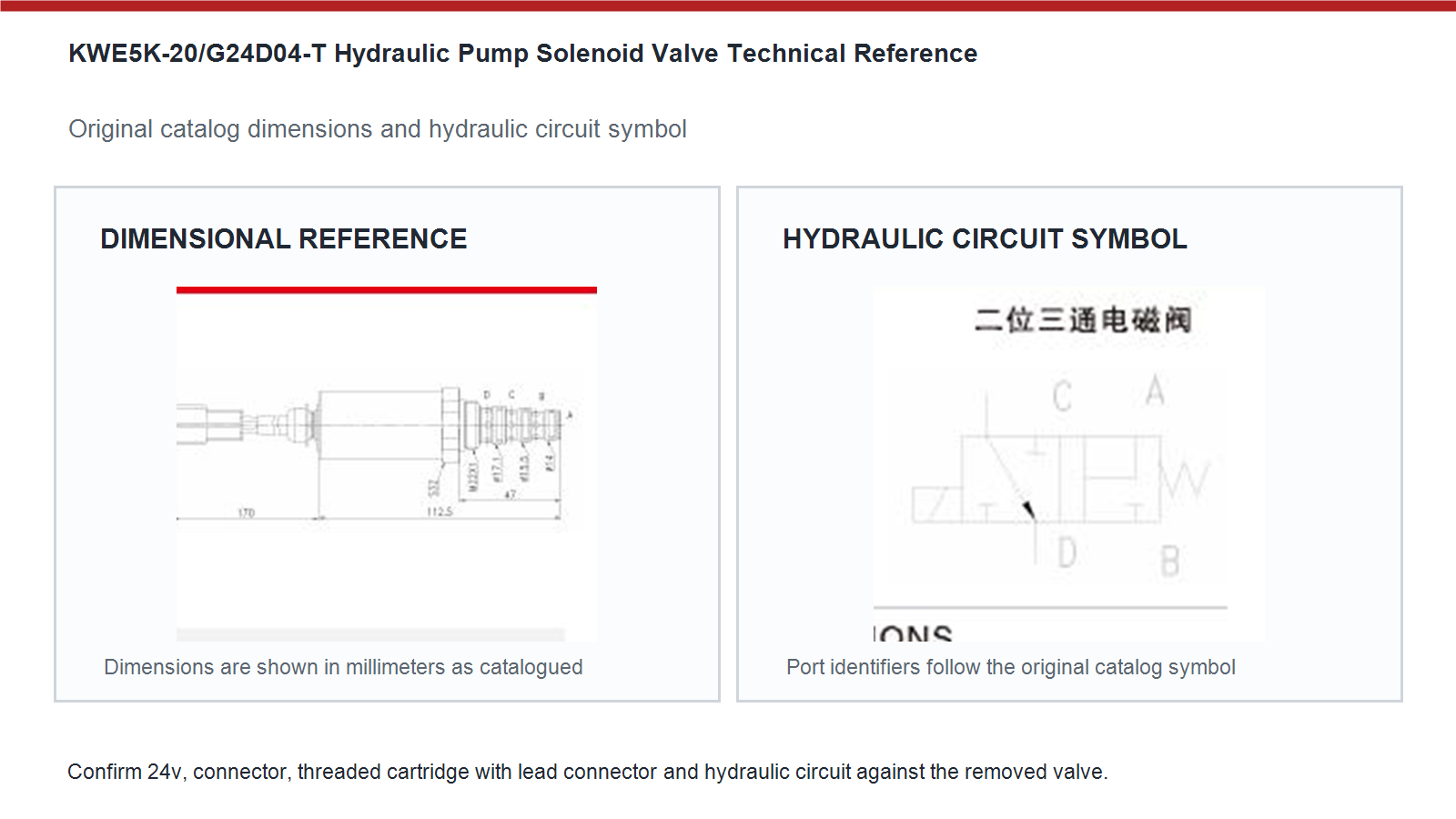
Complete every control point below before a sample or bulk order is released.
Approval Point |
Buyer Review |
|---|---|
Reference |
KWE5K-20/G24D04-T |
Electrical |
24V; verify at the loaded connector |
Mechanical |
Compare threaded cartridge with lead connector, sealing positions and installed clearance |
Hydraulic |
Confirm normal state, energized state and port relationship |
Machine Evidence |
Kato HD820 hydraulic pump control using the complete KWE5K-20/G24D04-T marking |
Separate electrical command, component movement and final machine response so the actual wiring or hydraulic fault is not hidden by parts replacement.
Observed Condition |
Recommended Check |
|---|---|
No movement |
Check loaded connector voltage, ground, controller command and coil resistance. |
Slow response |
Inspect oil cleanliness, filter condition, viscosity and valve movement. |
Reversed response |
Stop operation and compare normal and energized port logic. |
External leakage |
Inspect seals, valve surface, bore condition and seating depth. |
Repeated heating |
Confirm voltage, duty cycle, connector resistance and full movement. |
When a machine harness revision is compared, keep the verified measurements and test result in the service record. Use the complete old marking, 24v electrical version, connector face, threaded cartridge with lead connector, sealing positions and the machine hydraulic schematic. A reference alone cannot prove that the normal and energized flow paths match. Record the machine model, serial number and removed-valve photographs with the approved sample so repeat orders follow the same engineering basis.
When export packing is approved, keep the verified measurements and test result in the service record. Read the voltage marking on the removed coil and measure supply at the loaded connector while the controller commands the valve. Do not infer voltage only from battery count because converters, harness changes and mixed fleets can produce another coil supply. Keep the confirmed value on the inquiry, purchase order, carton label and incoming inspection record.
When an installer measures unexpected voltage drop, keep the verified measurements and test result in the service record. Treat 240 bar catalog reference as a component reference that must remain within the actual circuit requirement, not as permission to ignore the machine service data. Confirm which ports see pressure in both switching states, review return pressure and verify the cavity or flange. Pressure capability cannot correct a wrong spool function, cartridge depth or manifold relationship.
When a machine harness revision is compared, keep the verified measurements and test result in the service record. Compare overall length, thread or flange position, sealing diameters and connector clearance with the removed component. Read the spring side of the hydraulic symbol as the normal state and the solenoid side as the energized state. Reconcile catalog port letters with the equipment schematic before commissioning because labels can differ between valve and machine drawings.
When a customer reports intermittent operation, keep the verified measurements and test result in the service record. Serial evidence is essential whenever one equipment family used more than one pump, manifold or harness revision. Use it with the parts diagram rather than as a substitute for physical checks. If the old label is damaged, collect connector, mounting, cartridge and installed-location photographs so the application can be narrowed without guessing from the machine name.
When cold-start commissioning is completed, keep the verified measurements and test result in the service record. Fine debris can restrict the moving element, damage sealing lands or block a pilot passage even when the coil energizes normally. Review the filtration requirement, inspect the removed valve for particles and flush the affected circuit when contamination is found. Replacing the valve without correcting dirty oil can reproduce slow response, sticking or repeated electrical stress.
When a return analysis starts without machine records, keep the verified measurements and test result in the service record. Measure voltage across the coil while the controller commands the valve, then measure positive and ground-side drops separately. A static open-circuit reading can appear normal while a corroded terminal collapses under load. Compare the result with 24v and repair excessive resistance before judging the valve itself as defective.
Send the complete old marking or component evidence, confirmed voltage, machine information, clear photos, measurements and required quantity for a fitment-focused B2B quotation.


