
English


40237514
40237514
OE-Equivalent Replacement Quality
IATF 16949 / ISO 9001 / CE / RoHS
50 pcs
7 - 15 Days
12 Months
40237514
Heavy equipment hydraulic valve blocks using the same reference, cartridge and circuit configuration
Confirm voltage, connector, cartridge or flange dimensions, seals and hydraulic circuit before installation.
| Quantity: | |
|---|---|


40237514 is catalogued as a 24V hydraulic cartridge solenoid valve with a 7/8-14 UNF interface and 240 bar maximum working pressure. Confirm the removed cartridge, connector, energized flow path and equipment record before release.
Item |
Confirmed Information |
Product Type |
Hydraulic cartridge solenoid valve |
OE / Reference Numbers |
40237514 |
Voltage |
24V |
Application Scope |
Heavy equipment hydraulic valve blocks using the same reference, cartridge and circuit configuration |
Electrical Version |
24VDC |
Thread |
7/8-14 UNF-2A |
Maximum Working Pressure |
240 bar |
Filtration |
25 micrometres or better |
Operating Temperature |
-40 to +120 degrees Celsius |
Installation Torque |
34 to 37 Nm |
MOQ |
50 pcs |
Delivery Time |
7 - 15 Days |
Warranty |
12 Months |
Use the 40237514 dimensional and circuit image to compare cartridge depth, sealing-land alignment, connector clearance and hydraulic port behavior.
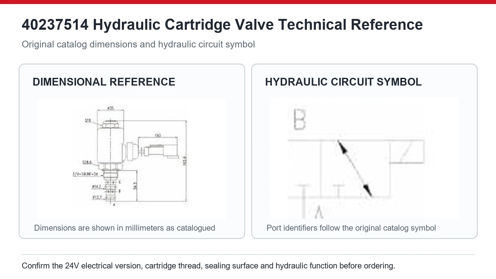
Control 40237514 approval through its 24V coil, 7/8-14 cartridge geometry, sealing positions, 240 bar duty and the actual valve-block circuit.
Approval Point |
Buyer Review |
Reference Control |
40237514 |
Electrical Control |
24V; verify at the connector under command |
Mechanical Fit |
Compare thread or flange, cartridge length, sealing lands and installed clearance |
Functional Control |
Confirm normal state, energized state and hydraulic port relationship |
Application Evidence |
Heavy equipment hydraulic valve blocks using the same reference, cartridge and circuit configuration |
Slow or leaking operation should be traced through coil voltage, oil cleanliness, spool freedom, cartridge seating and cavity condition before component rejection.
Observed Situation |
Recommended Check |
No hydraulic response |
Check command voltage, connector, coil and whether the cartridge moves. |
Slow response |
Review oil cleanliness, filter condition, viscosity and connector voltage under load. |
Reversed response |
Compare normal and energized circuit states with the machine schematic. |
External leakage |
Inspect seals, cartridge surface, bore condition and seating depth. |
Repeated coil heating |
Check voltage, resistance, duty cycle, contamination and incomplete spool movement. |
Approval Item |
Required Information |
Old Part Evidence |
Complete label, connector face, mounting or cartridge side and one installed view |
Machine Evidence |
Heavy equipment hydraulic valve blocks using the same reference, cartridge and circuit configuration |
Measurements |
Thread or flange, cartridge length, seals and installed clearance |
Electrical Evidence |
24V; measured under the actual command |
Commercial Evidence |
Quantity, destination, packing, labeling and inspection requirements |
Read the voltage marking on the removed coil and measure supply at the connector during a real command. Compare connector keying and coil resistance with the approved 40237514 sample. Keep 24V on the inquiry, purchase order and receiving label so a visually similar coil from another voltage family cannot enter the same stock location.
Hydraulic cartridges with the same 7/8-14 thread can have different pressure ratings and internal designs. The 40237514 specification lists 240 bar, so system pressure and circuit duty must remain within the approved application. Do not substitute a valve solely because another unit shares the thread or a higher-looking pressure figure without confirming circuit behavior and geometry.
Cartridge length, nose shape, sealing-land spacing, port openings and normal valve state may all differ. Measure from the shoulder to each sealing feature and compare the old unit directly. A cartridge may tighten normally yet block or connect the wrong valve-block passages, creating leakage, no response or unexpected machine movement.
Use the complete reference and the actual valve-block configuration. Record connector, 24V supply, cartridge measurements, seals, circuit symbol and normal versus energized response from the removed unit. Link the approved sample to the equipment serial record internally, but release supply from component evidence rather than adding an unsupported broad machine application.
Inspect supply voltage under load, connector resistance, oil viscosity, filter condition and spool freedom. The specified filtration is 25 micrometres or better. Contamination can delay movement or keep the cartridge partly open, while low coil voltage reduces magnetic force. Diagnose electrical and hydraulic conditions before deciding that the new valve is faulty.
Depressurize the system, then inspect seal size and condition, cavity finish, cartridge seating depth and applied torque. Confirm that 34 to 37 Nm was reached only after the thread engaged smoothly. External leakage often results from cut seals, contamination or bore damage, while internal leakage may indicate an unsuitable circuit or sealing-land position.
Provide 40237514, measured 24V supply, valve-block photographs, cartridge and seal dimensions, circuit details, operating pressure, quantity and delivery location.


